13 MTS_OW100_IFU-orthogold100-US-K182682_A
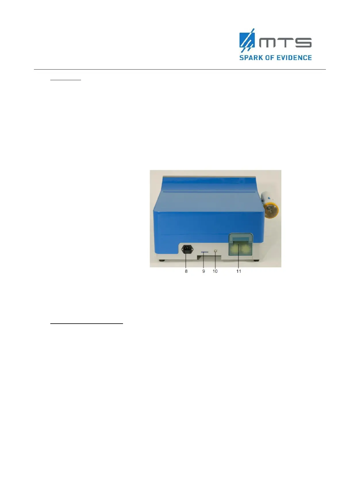
Rear View
The power supply socket (8) serves to connect the delivered power cable.
The use of the memory card slots (9) is meant only for service purpose. The
memory card stores the technical errors appearing during operation and the Log-
files.
The USB connector (10) is also meant only for service purpose only.
The water cartridge (11) (should be exchanged according to the request of the
device).
8 Connecting socket for the
detachable power cable
9 Slot for the memory card (only for
service purpose)
10 USB connection (only for service
purpose)
11 Water cartridge
Figure 3
Components and connections of the OW100
®
at the rear side
Acoustic wave generator
The acoustic wave generator full fills the following tasks:
Creation and control of the high voltage for the discharge at the electrode.
Creation and control of the trigger signal. The OW100
®
commands the following
trigger modes:
Acoustic wave release per footswitch
Acoustic wave release per button at the applicator
The acoustic wave release frequency varies between 0.5 to 8 pulses (acoustic
waves) per second.
 Loading...