Home
MTS Systems
Medical Equipment
OrthoGold100 OW100-US
Page 7
MTS Systems OrthoGold100 OW100-US - Page 7
70 pages
Manual
Save Page as PDF
To Next Page
To Next Page
To Previous Page
To Previous Page
Loading...
7
MTS_OW
100_IFU-orthogold100-
US
-K182682_A
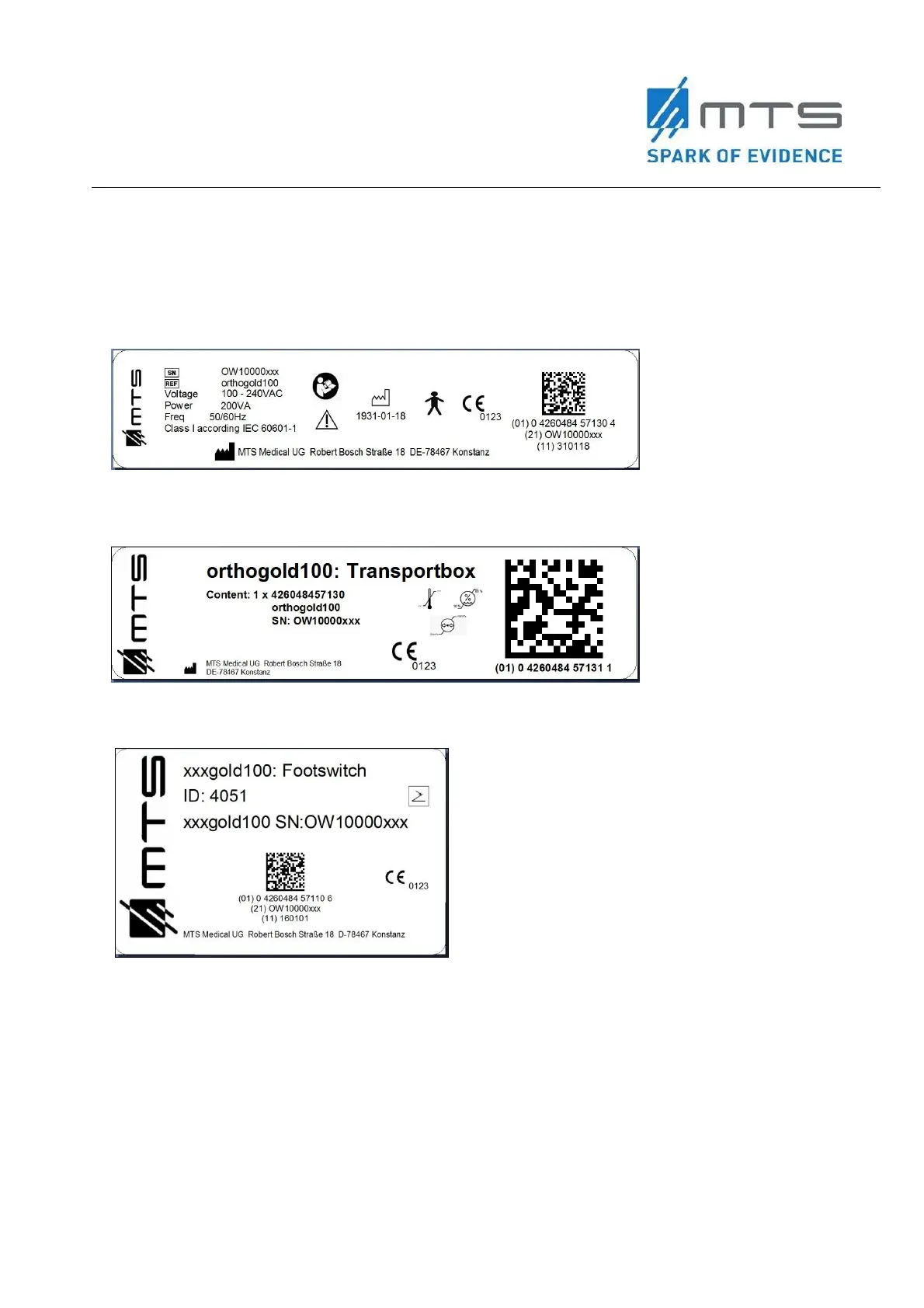
The following la
bels are attached to the dev
ice or the
applicator:
Type plate o
f
the ba
sic unit,
exe
m
pli
fied:
Type plate o
f the transport box,
exemplified:
Type plate o
f the footswitch,
exe
m
pli
fied:
6
8
Table of Contents
Main Page
Default Chapter
2
Table of Contents
2
Glossary
5
Symbols Used in this Document
5
Symbols Used on the Product Labels
6
1 Introduction
9
2 Device Information
9
Indications for Use
9
Contraindications
9
Warnings
10
Cautions
10
Device Description
11
Figure 1 Function Principle of Acoustic Wave Creation with the OW100
11
Figure 2 Components and Connections of the OW100 at the Front Side
12
Figure 3 Components and Connections of the OW100
13
Figure 4 Applicator
14
Figure 5 Water Cartridge of the OW100 at the Rear Side
15
Figure 6 Front Side Connections of the OW100
16
Figure 7 Connections at the Rear Side
17
Figure 8 Applicator Connection Socket (Left) and Connect Applicator (Right)
18
Figure 9 Display of the OW100
18
Figure 10 Touch Panel (Left) and Touch Wheel (Right) of the OW100
19
Figure 11 Footswitch
19
3 Set-Up Instructions
20
Table 1: List of Delivered Parts with the OW100
21
Figure 12 Installation of Power Supply
22
Applicator
23
Figure 13 Applicator Connection - Inside View (Left) and Socket (Right)
24
Figure 14 Connected Applicator
24
Figure 15 Display of the Connected Applicator at the OW100
24
Applicator Connection
25
Changing and Disconnection of Applicator
26
Figure 16 Applicator Drain Control
28
Water Cartridge
29
Figure 17 Pit for Water Cartridge (1)
29
Figure 18 Unlocked Water Cartridge
29
Figure 19 Inserted and Locked Water Cartridge (2)
29
Figure 20 Water Cartridge of the OW100 Shown from above (Left) and from Front Side (Right)
30
Connect the Footswitch
31
Figure 21 Set-Up Menu of the OW100
31
Figure 22 Connected Footswitch
31
Menu Setup
32
Figure 23 "SETUP' Key Field
32
4 Operating Instructions
33
Figure 24 Power Switch Activated
37
Figure 25 Step 3 - When to Press the Confirmation Button
37
Figure 26 Start Screen of the OW100 with Displayed Software Version
37
Figure 27 Operation Screen
38
Figure 28 "FILL" Key on the Display
39
Setting the Output Parameters
43
Figure 29 Touch Panel of the OW100
44
Figure 30 Touch Wheel of the OW100
45
Figure 31 Options for "ENERGY" on the Display
45
Figure 32 Beam Pressure Maximum and Target Location
46
Figure 33 Dependence of the Pressure Pulse Parameters on the Generator
47
Figure 34 Dependence of the Acoustic Pulse Energy on the Generator
48
Figure 35 Dependence of the Pressure Pulse Parameters on the Generator
48
Figure 36 Setting the Frequency at the Display
49
Figure 37 Pre-Set of the Number of Shots for One Treatment
50
Figure 38 Display of the Connected Applicator Types at the Display of the OW100
50
Acoustic Wave Treatment
51
Figure 39 Display of the Remaining Acoustic Waves on the Applicator
51
5 Emergency Procedures
55
6 Cleaning Instructions
55
Maintenance
55
Storage
56
Disposal of the Device
56
7 Technical, Electrical, & EMC
57
Electrical and EMC
57
Table 2 Recommended Safety Distances between Mobile HF Telecommunication Devices and the OW100
57
Table 3 Electromagnetic Interference
59
Table 4 Resistance to Electromagnetic Interference
60
Table 5 Guidance and Manufacturer´s Declaration
61
Standards
63
8 Troubleshooting
64
Table 6 Troubleshooting Issues
64
Figure 40 Example of an Error Message. the Picture Shows, that There Are Several Error Messages Piled up
66
Figure 41 Example of a Warning Message
66
Figure 42 Example of Information Error
66
9 Additional Information
67
Ordering
67
Product Liability & Warranty
67
Transport
67
Return for Service
68
Closed (Left), Opened with Device (Right)
68
Figure 44 Applicator Packaging Opened. Send Back the Used Applicator and the Water Cartridge
69
Related product manuals
MTS Systems 111 Series
20 pages
 Loading...