COCKPIT SX
Page 70
16.8.3. Checking the heading function
You can check that the gyro in your model switches to
heading mode using this procedure:
Requirements:
a. GYRO = -50%
(gain Î 16.8.1.)
b. HEADG = 1
(heading activated Î 16.8.2.)
Checking:
Move the yaw stick briefly to one end-point, then re-
lease it again.
a. When you release the stick, the tail rotor blades
stay in position or run back to the starting point
very slowly:
gyro working in heading mode
b. When you release the stick, the tail rotor blades
immediately return to the starting point:
gyro working in normal (damping) mode
In this case you must reverse the control signal at
channel 6.
(Brief instructions, servo reversing Î 16.4.1.)
Further effects of heading mode:
a. The mixing of collective pitch to tail rotor
(tail rotor compensation / Revo mix Î 16.7.4.)
is switched off.
b. Any OFFSET (Î 16.7.5.) you have set is ignored.
16.9. Transmitter control settings
Dual Rate and Exponential
for ROLL, PITCH-AXIS and YAW
16.9.1. Setting Dual Rate for roll, pitch-axis and
yaw
Menu: (
CONTRL) DR
For each position of the D-R switch you can set differ-
ent rates of travel (Dual Rates) for the three transmitter
controls roll, pitch-axis and yaw.
The Dual Rate function of the C
OCKPIT SX has two
purposes:
• Assigning two different rates of effect to a stick.
Example: for fine control when flying, the stick res-
ponse only needs to be 50%. In extreme situations
the D-R switch is operated to select full travel.
• Adjusting the effect of the transmitter control when
that control is used as part of a mixer.
Example: the swashplate servos are actuated in
common by COLLECTIVE PITCH, ROLL and PITCH-
AXIS. The magnitude of the effect of the collective
pitch stick is determined by the collective pitch curve
(Î 16.5.). For roll and pitch-axis you can adjust the
effect using the Dual Rate function. 50% is sufficient
in most cases.
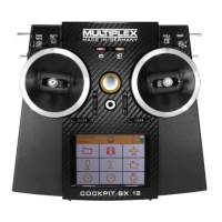
Moving to the DR menu:
4 to MENU, r (SETUP appears),
3 to CONTRL, r (DR Q appears), r
The current setting flashes. Our example shows the
Dual Rate setting for Q = ROLL. Use the 3-D digi-
adjustor to select the desired value within the range
100% to 25%. The minimum value of 25% avoids the
danger of accidentally switching off a control entirely
(0%).
Important:
This setting only applies to the current position of the
D-R switch! Check this by switching to the second
value.
A brief press r on the 3-D digi-adjustor concludes the
process. The value is stored.
TIP: If you do not wish to use the D-R switch,
simply set the same values for both switch posi-
tions. This will protect you from unwelcome sur-
prises if the switch happens to be in the wrong
position.
Important: use of flight phases
If you have activated flight phases (Î 16.10.2.), you
can set different values for each flight phase. The flight
phases are selected using the A-ROT and PH
switches. The screen displays the currently selected
phase (Î 16.10.3., table 2).
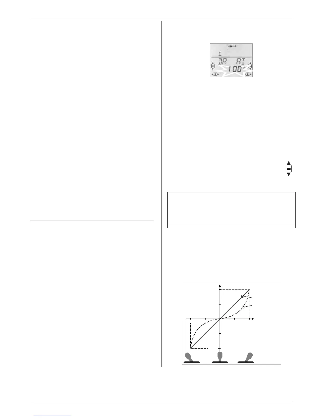
16.9.2. Adjusting the Exponential function
Menu: (
CONTRL) EXP
The Exponential function is used to provide finer stick
response around the centre position. In contrast to
Dual Rates, however, servo travel is unchanged at the
stick end-points.
The following diagram shows the effect of Exponential.
+100%
+50%
+100%
+50%
-100%
-100%
Normal (EXP 0%)
EXP -100%
Servo travel
TRAVL
Stick travel
123