COCKPIT SX
Page 72
A-ROT
switch
PH
switch
Display
1
123
2
123
OFF
forward
3
123
The code number of
the active phase is
displayed con-
stantly; the other
two flash.
ON
back
auto-
rotation
any
123
All three code num-
bers flash.
Table 2: Flight phase indication in the menus
16.10.4. Copying flight phases
Menu: (
PHASES) COPY
The destination for the copy is selected in the menu.
The source is always the current flight phase, which
you have selected using the A-ROT and PH switches.
Moving to the Menu:
4 to MENU, r (SETUP appears),
r (MODEL appears), r (MODE appears),
3 to PHASES, r (current value appears),
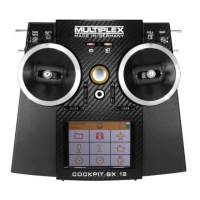
3 to COPY, r
The number 0 flashes in the bottom line. Select phase
1 to 4 as destination using the 3-D digi-adjustor.
Check once more that you have selected the correct
source using the PH and A-ROT switches (Î table 1 in
section 16.10.3.).
A further brief press r on the 3-D digi-adjustor triggers
the copy process, and the flashing ceases.
Note: interrupting without making a copy
If you leave 0 as the destination, no copy will be made.
16.10.5. Setting the transition speed for switching
flight phases
Menu: (
PHASES) SPEED
The SPEED parameter can be adjusted to determine
the speed of transition from one flight phase to another.
Four settings are possible:
SPEED
Transition
0
immediate
1
fast approx. 1 sec
2
moderate approx. 2 sec
3
slow approx. 3 sec
Exception: Auto-rotation
If you switch to auto-rotation from flight phase 1, 2 or 3
the transition is always immediate, regardless of the
transition SPEED you have set.
Moving to the SPEED menu:
4 to MENU, r (SETUP appears),
r (MODEL appears), r (MODE appears),
3 to PHASEN, r,
3 to SPEED, r
The current setting flashes. Select the desired value
using the 3-D digi-adjustor (see table above).
A brief press r on the 3-D digi-adjustor concludes the
process. The value is stored.
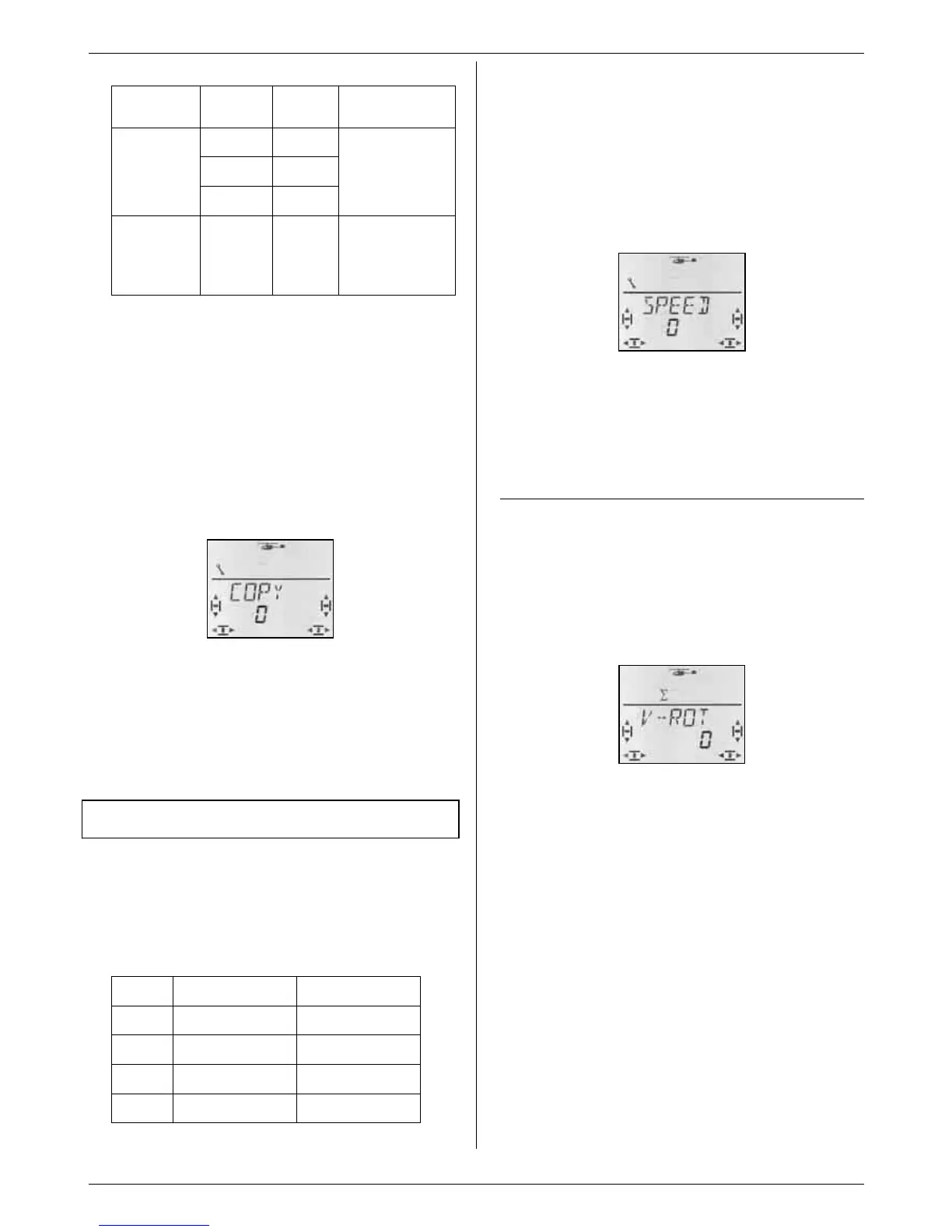
16.11. Virtual swashplate rotation
Menu: (MIXER ROTOR) V-ROT
Virtual swashplate rotation electronically “rotates” the
swashplate. The purpose of this function is to prevent
the helicopter veering to one side when you apply a
PITCH-AXIS command.
Moving to the V-ROT menu:
4 to MENU, r (SETUP appears),
3 to MIXER, r (TAIL appears),
3 to ROTOR, r (V-ROT appears), r
The current value flashes in the bottom line. Use the 3-
D digi-adjustor to set a value within the range -100° to
100° (the “°” character is not displayed).
Negative values rotate the swashplate anti-clockwise,
positive values rotate it clockwise.
A brief press r on the 3-D digi-adjustor concludes the
process. The flashing ceases, and the value is stored.
V-ROT for other tasks
Even if the swashplate linkage is not in accordance
with the requirements stated in section 16.3.4., you can
still make adjustments using V-ROT.