MCD100-155E
MCD100
MCD155
MCD120
MCD140
B
B
30
244
304
30
450
510
140
(2x)
162
(3x)
12
12
M8 (10x)
502
450
26
134
(2x)
12
239
(2x)
291
231
30
M8 (8x)
C
C
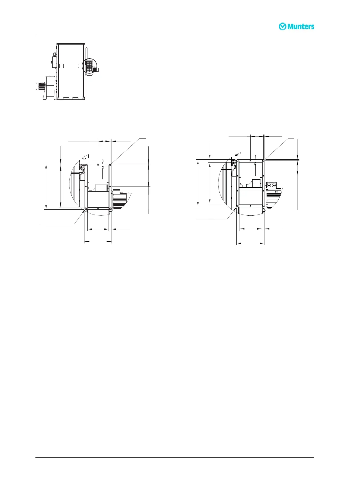
Figure 3.30 Reactivatio n a ir outlet (wet air outlet)
C: Use hexagon head bolts (M8 x 25).
3.9 Electricalconnections
Thedehumidifier is designed for operation with a three-phase four wire system. All dehumidifiers are
delivered complete w ith all internal wiring installed and configured in accordance with the voltage a nd
frequency specified on the identification plate.
The mains power supply is connected directly to the main power switch in the unit. The supply cable
and main fuses must be dimensioned to suit the unit being installed. For connection details, refer to the
identification plate and w iring diagram, or to section 7.4, Technical data.
NOTE!
Thesupplyvoltagemust notdifferfromspecifiedoperating voltage by morethan+/-10%.
190TEN–106 5–J1408
Installation
23