7.2.3 MCD140E
BCD
1
2
3
4
3
2
4
1
3
2
4
1
3
2
4
1
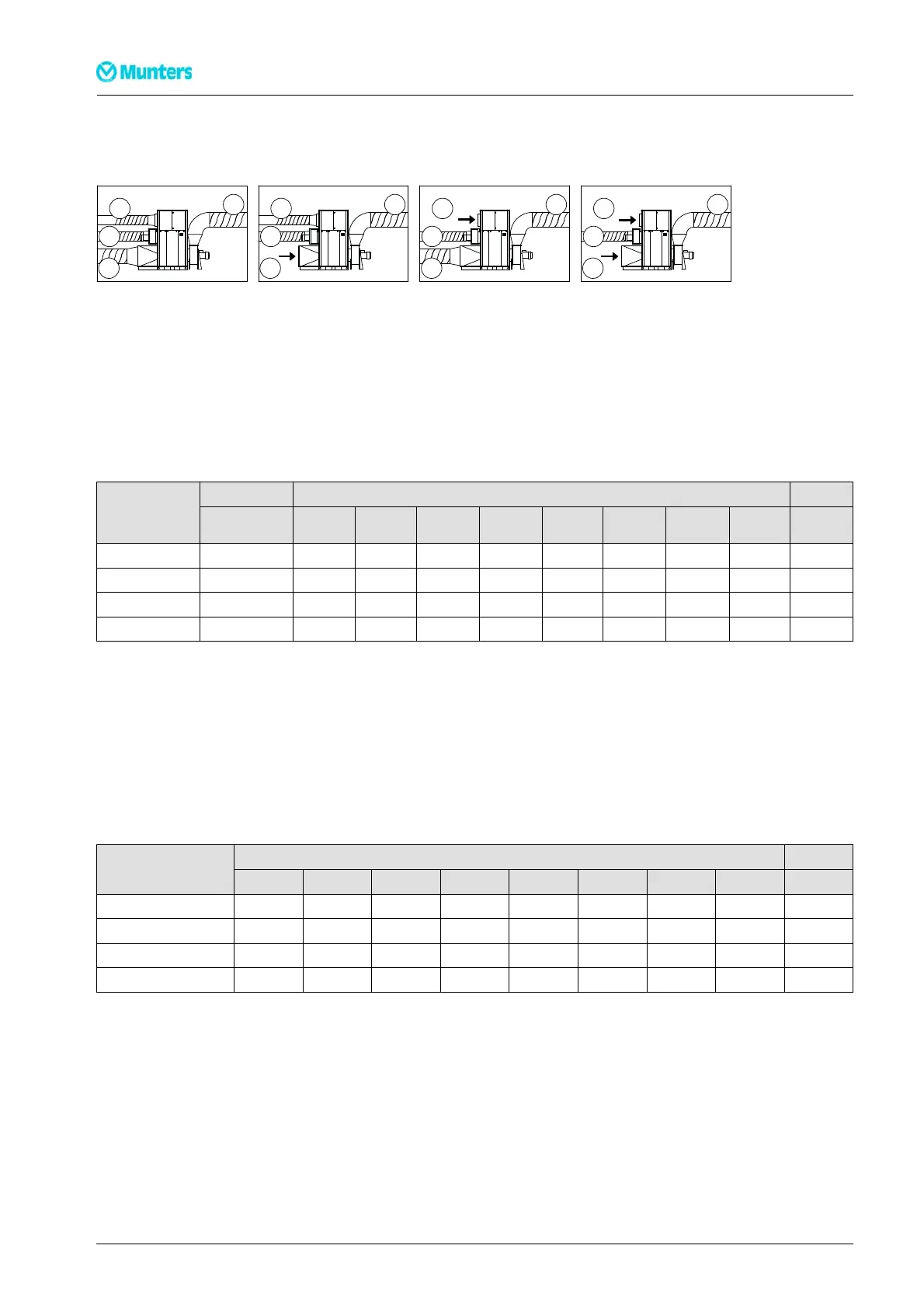
A
SetupA:Allductsconnected 1. Ductworkfordryair
SetupB:Processinletnotconnectedtoduct 2. Ductworkforprocessair
SetupC:Reactivationinletnotconnectedtoduct 3. Ductworkforreactivationair
SetupD:Reactivationandprocessinletnotconnectedto duct 4. Ductworkforwetair
Noise to r oom
CorrectionKokdBatISO-bandcentrefrequency,Hz
Setup
Lp(A)100m
2
Lwt
(dB)
63 125 250 500 1000 2000 4000 8000
A 81 103 -6 -3 -12 -14 -12 -16 -17 -20
B 83 103
-7
-3 -11 -8 -12 -17 -18 -20
C
81 103 -6 -2 -13 -15 -12 -17 -18 -21
D 83 104 -6 -3 -12 -9 -13 -15 -18 -20
Table7.5Noisetoroom
Lp(A) 100 m
2
= Rated pressure sound level at 100 m
2
room abs o rption (A–weig hted).
Lwt = Total sound power level (db) (rel. 10–12 W)
Kok = Correction for calculating Lw (Lw = Lwt + Kok)
Noise in ducts
Corre c tion Kok dB at IS O-band c e ntre frequency,Hz
Ductwork
Lwt(dB) 63 125 250 500 100 0 2000 4000 8000
1. Dry air 114
-5
-4 -8 -10 -14 -20 -26 -33
2. Processair 96 -2
-5
-12 -18 -24 -30 -39 -47
3. Reactivationair 93 -1 -8 -23 -22 -29 -33 -38 -51
4. Wetair 106 -8 -4 -8 -6 -14 -17 -23 -30
Table7.6Noiseinducts
40
Technicalspecification
190TEN–106 5–J 1408