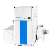
4 Commissioning
WARNING!
Commissioningandinitialstart
-upoftheunitshouldbe carried outbyMunterspersonnelonly.
WARNING!
Themainspowersupplyispermanentlyconnected tothe main power switch oftheunit. Riskofelectric shock.
4.1 Pre-startchecks
1. Make sure that the main power switch on the control panel is in the 0 position.
2. Make sure that the air intake filt ers are undamaged and correctly installed and that all areas inside the
different unit sections are clean.
3. Examine all ducts and duct connections and make sure that all connections have been correctly installed,
and that the re are no sig ns of damage to the system. Make sure tha t all ducts ar e free from u nwante d
material blocking the air passage.
4. Make sure that the humidity transmitter is correctly positioned in the duct, and corr ectly connected to
the dehumidifier, see section 3.10,Externalhumiditytransmitter.
5. Open the cover for the electrical panel and make sure that no circuit breakers or automatic fuses have
tripped. For m ore information, refer to the w iring diagram provided with the unit.
6. Make sure that the incoming power supply voltage is cor rect and that the cables are cor rectly connected.
7. Set the main power s wit ch to position 1.
8. Star t the unit by setting the mode switch to position MAN.
9. Make sure that the rotor rotates in the direction indicated by the ar rows. If the direction of rotation is
wrong, interchange the connections for the incoming w ires in the main power switch.
10. Switch off the unit a nd continue with the procedure in section 4.2, Airflow adjustment.
4.2 Airflowadj ustment
4.2.1 General
To obtain optimal performance, the process and reactivation airflows must be cor rectly adjusted in
accordance with the rated airflows, see 7.4, Technical data.Theairflows can be set in the control system display
without using dampers.
For more information about the control system, parameters and settings, see the control system
supplement.
Contact M
unters for help with installation and settings. For contact addresses, see section 9, Contact M unters.
NOTE!
Th
eapplication softwaresettingsforthe frequencyconverter aresetat thefactory. The frequency control
rangeis
limitedtocorrespondtoanacceptablefanspeed.
WARNING!
Rotatinghazard–toprevent access tothe fanimpellersthedehumidifiermustonlyberunwith thewetanddryair
ductsconnected.
190TEN–106 5–J1408
Commissioning
25