5 Operat ion
5.1 C ontro lpanel
RUN
SERVICE
ALARM
1
2
34
0
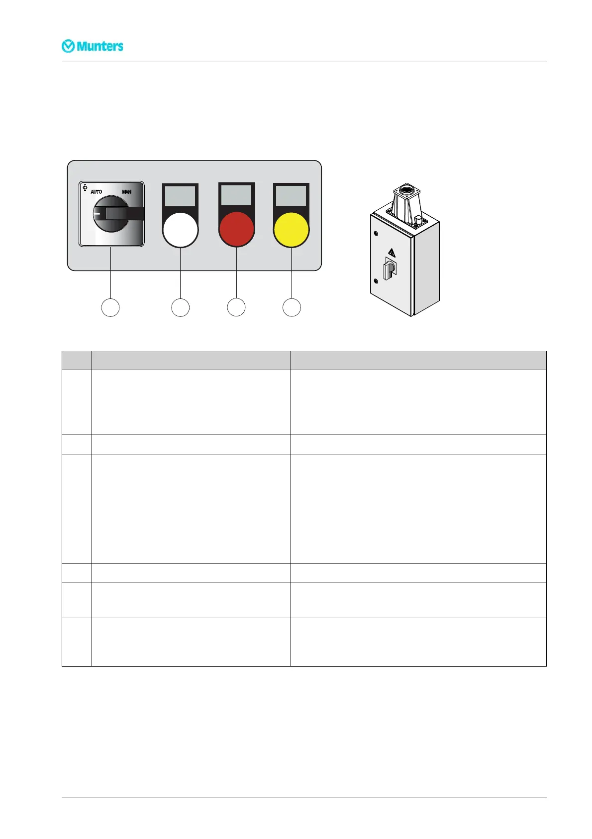
Figur e 5.1 Control panel Figure 5.2 M ain power switch
Item Switch/Indicator Function
Main power switch(see
Figure 5.2
) Whenthe mainpowerswitchisin position0,the unitisnotpowered
beyondtheswitch.
Whenthe mainpowerswitchisin position1,the dehumidifiercanbe
started.
Controlandregulationsystem (HMI) Seethesupplement forinformationon HMI operation.
1 Mode switch Whenthe modeswitchisin position MAN,thedehumidifierruns
continuously(fullcapacity). Thereis abriefdelay beforetheunitstarts.
Whenthe modeswitchisin positionAUTO,thedehumidifieris regulated
byaninternaladjustablehumiditylevelset-point,or viaanexternalinput
signal.
Whenthe modeswitchissetat0 , thedehumidifier isswitchedoffbut
continuestorununtilithas cooleddown.
2 Whitelamp (RUN) Lightswhenone ofthe fans isrunning.
3 Red lamp (ALARM) Illuminateswithasteady glow whenan alarmhasbeen triggered. Check
whichalarm has been triggered.
4 Yellow lamp(SERVICE) Lightswhena filterchangeis required,orwhen the dehumidifierhas
reachedthenumber ofoperatinghours orthedateat whichmainte-
nanceshould be carriedout,seesection
6.5, Service indicator lamp
.
Table 5.1 Control panel functions
28
Opera tion
190TEN–106 5–J 1408