Operation
User manual 55530_hdb_en_16 130 / 156
9 Operation
9.1 LED indications
All MVK-MPNIO have separate and clearly arranged indicators:
LED indication for inputs and outputs
LED indication for bus
LED indication POWER
Extended LED indications
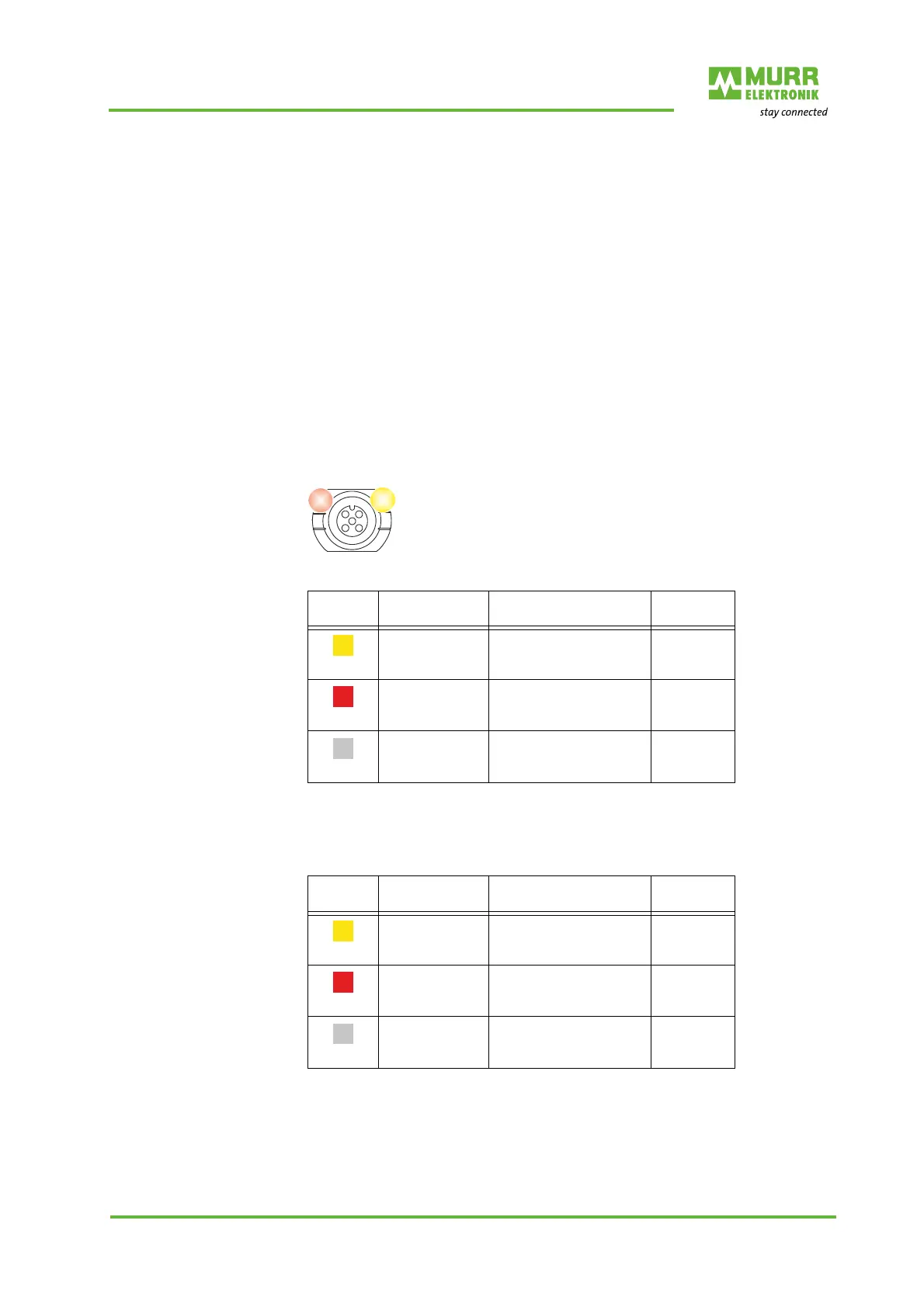
To identify the displayed information clearly, the LEDs on the front panel of the
module are labeled. The indication is performed by means of a continuous
light or flashing of the LEDs. The following figure shows the arrangement of
the LEDs and the table shows the functions.
LED indication
Digital inputs
Tab. 9-1: LED indication digital input
LED indication
Digital outputs
Tab. 9-2: LED indication digital outputs
Error at input or output In the event of an error (short circuit or overload) at the digital output or the
sensor power supply, the relevant LEDs light up red at the M12 port.
A separate status display is assigned to each in-
put and output.
Indica-
tion
State Voltage at input Logical
value
Yellow
Continuously lit 24 V 1
Red
Continuously lit - 0
Off
0V 0
Indica-
tion
State Voltage on
output
Logical
value
Yellow
Lit continuously 24 V 1
Red
Lit continuously 0 V 1
Off
0 V 0
 Loading...


