18
5.2.3 CONFIGURING OUTPUTS
Output Mode
Therearetwowaystoconguretheoutputs.AllcongurationisdonethroughthesamePGN.PGN61408isusedformultiple
messagesbyuseofadierentvalueputintothe“command”byteofthePGN.Thisvalueisusedaanindexorpointerastowherethe
informationgoesinthemodule.
A. Global Output Conguration
(onlyusedifyouwantalltheoutputstobeconguredthesame)
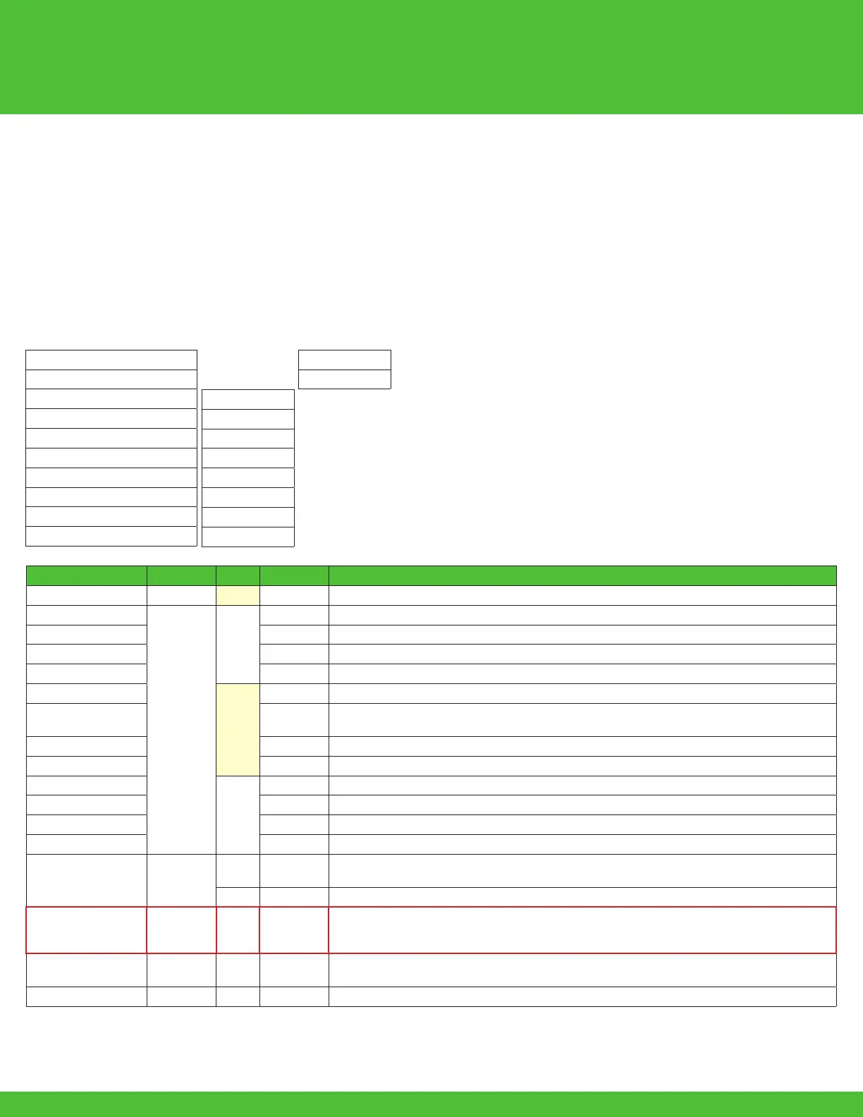
Conguringalloftheoutputsisdonethroughthe“MODE1”byteinPGN61408.TheJ1939messagestructure,
The frequency set point must be greater than 0 for any output to function.
PGN
61408(0xEFE0)Nodeosetof0
Source Address
(0x??(CSA*))
PDU Format
239(0xEF)
PDU Specic
224(0xE0)
Built Message
(0x18EFE0??)
Transmit rate
50 ms
Msg timeout
200 ms
Priority
6
DP
0
Command Value
82(0x52)
Name Data Type Byte Bits Description
Command Byte 1 Commandforindexpointer(whichmessageyoursending)
CtrlModeReset
2 bit
2
1,2 EnablesControllerModeOutputReset
EnableStatus1Msg 3,4 Enablestheconstanttransmissionofstatusmessage1
EnableStatus2Msg 5,6 Enablestheconstanttransmissionofstatusmessage2
EnableAmpMsg 7,8 Enablestheconstanttransmissionofamperagemessages
Enable24VDC
3
1,2 Enablesthelowandovervoltagefaultlimitsfor24VDCsystem
SaveConguration 3,4
Savesthecongurationtothemodule(otherwisechangesonlyvaliduntilapowercycleoccurs),
setto1towritecongurationtomodule
Analograwvalue 5,6 Internal Use Only
7,8
4
1,2
3,4
5,6
7,8
FREQ1 Word
5
Setstheglobalcongurationofthefrequencyforallchannels.
LowByteFREQ1:Valueindecimal(40-1100Hz).Example:0xC8h=200d=200Hz.
6 HighByteFREQ1
MODE1 4 Bit 7
SetstheglobalcongurationofALLtheoutputs,overides0x53hand0x54h.
0=Mode1NotUsed,1=ON/OFF,2=Data0-4000,3=Percent0-100.0%(0-1000),
(4=Amps(0-4000ma)Cannotbeusedinthismode.)
MODE2 4 Bit 7
Setsthecongurationoftheinputs.(0=Mode2NotUsed,1=DigitalPositive,2=DigitalGround)
No analog
ID1 Byte 8 UserdenedbyteforcongurationID,thiswillbetransimittedintheSTATmessage.
*CSA-ControllerSourceAddress
MODE1:See5.2.4fordescriptionofsettings.

 Loading...


