34
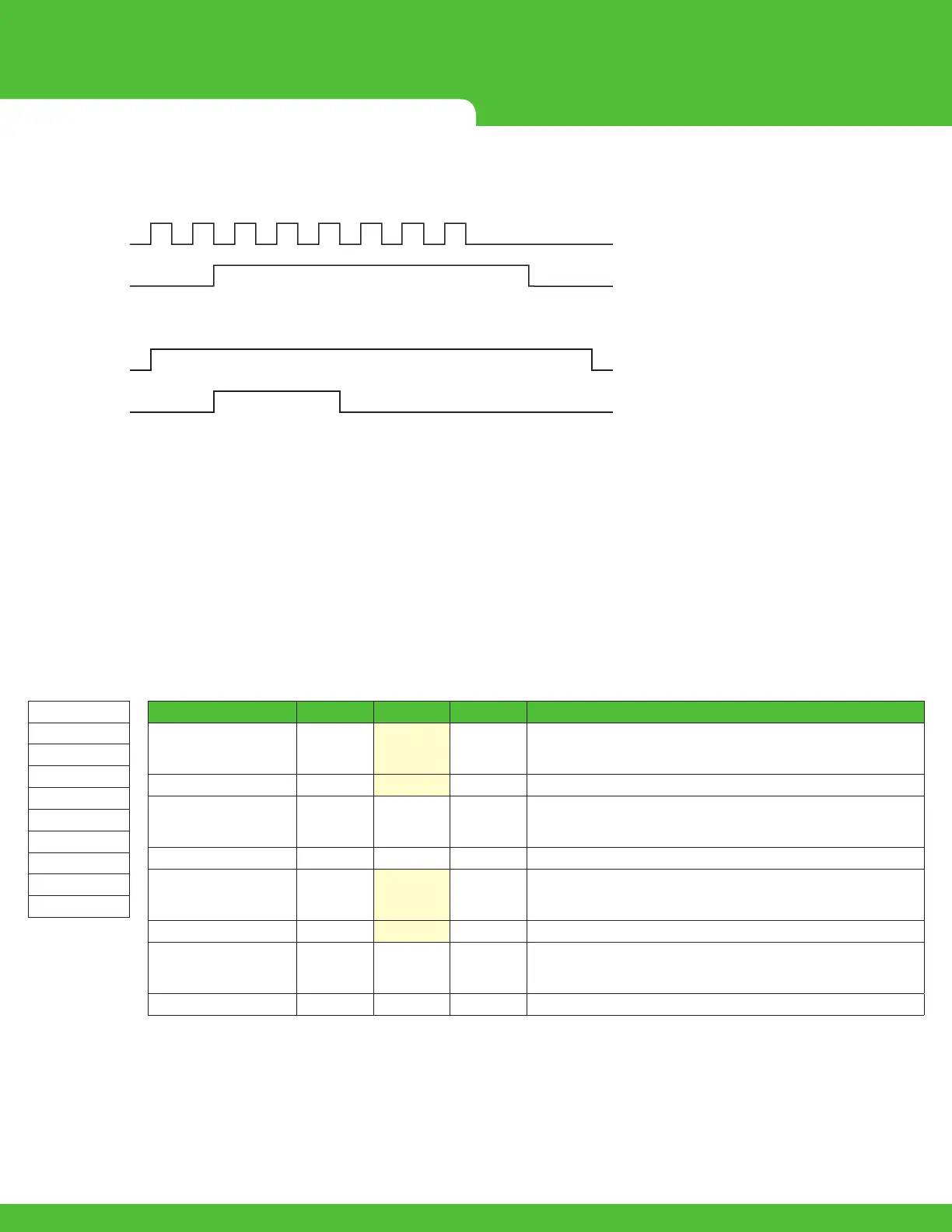
Counter - Roll Over and Output Enable
SetPointset,Reseto,RollOveron,OutputEnableon
1 2 876543
0 0 6665432100 0 666654321 6
0 3 3333333330 3 333333333 3
Counter Input
Counter On
Counter
Set Point
Output Command
Output Status
5.3.8 ENCODER OPERATION
•Input7A&8Aareusedforencodermode.ChannelAoftheencoderisconnectedtoInput7A&ChannelBisconnectedtoInput8A.
•Whentheencoderchannelsarecorrectlyconnected,asshownabove,rmwaretakescareofincrementingordecrementing
thecount.
•Thefunctionsthatworkwhenusingencodermodearetiedtocounter7A,theon/o&resetaretheonlycommandsthatworkat
thistime.
PGN
65307(0xFF1B)
Source Address
224(0xE0)
PDU Format
255(0xFF)
PDU Specic
27(0x1B)
Built Message
(0x18FF1BE0)
Name Data Type Byte Bits Description
Hertz_CountInput7A Word 1 Low Byte
Input7A,
Hertzisusedwhentheinputisconguredasafrequencyinput,
Countisusedwhentheinputisconguredasahighspeedcounter
2 HighByte
DutyCycle_SPInput7A Word 3 Low Byte
Input7A,
Duty Cycleisusedwhentheinputisconguredasafrequencyinput,
Set Pointisusedwhentheinputisconguredasahighspeedcounter
4 HighByte
Hertz_CountInput8A Word 5 Low Byte
Input8A,
Hertzisusedwhentheinputisconguredasafrequencyinput,
Countisusedwhentheinputisconguredasahighspeedcounter
6 HighByte
DutyCycle_SPInput8A Word 7 Low Byte
Input8A,
Duty Cycleisusedwhentheinputisconguredasafrequencyinput,
Set Pointisusedwhentheinputisconguredasahighspeedcounter
8 HighByte
A. The Count and Counter Set Point are shown in the message below/Encoder
InEncodermode,bytes1&2arethelowwordandbytes3&4arethehighwordtodisplaya32bitvalueoftheencodercount,
32bitsignedmaximumpositivecountis2,147,483,647.

 Loading...


