EN
W415-2350 / 10.28.19
9
venting
INSTALLATIONS
CANADA U.S.A.
A
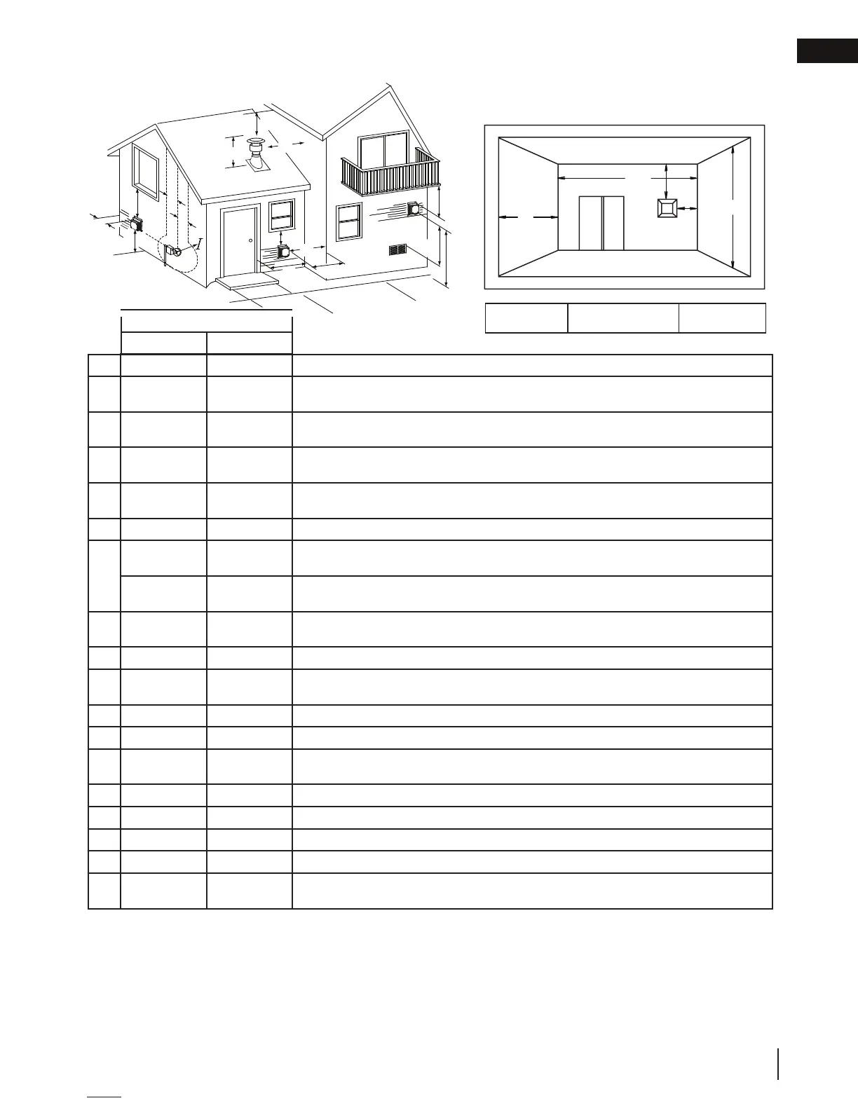
12” (304.8mm) 12” (304.8mm) Clearance above grade, veranda porch, deck or balcony.
B
12”
(304.8mm)
Δ
9” (228.6mm)
Δ
Clearance to windows or doors that open.
C
12”
(304.8mm)*
12”
(304.8mm)*
Clearance to permanently closed windows.
D
18”
(457.2mm)**
18”
(457.2mm)**
Vertical clearance to ventilated soffi ts located above the terminal within a horizontal distance of 2’
(0.6m) from the centerline of the terminal.
E
12”
(304.8mm)**
12”
(304.8mm)**
Clearance to unventilated soffi t.
F
0” (0mm) 0” (0mm) Clearance to an outside corner wall.
G
0” (0mm)*** 0” (0mm)***
Clearance to an inside non-combustible corner wall or protruding non-combustible obstructions
(chimney, etc.).
2” (50.8mm)*** 2” (50.8mm)***
Clearance to an inside combustible corner wall or protruding combustible obstructions (vent chase,
etc.).
H
3’ (0.9m) 3’ (0.9m)****
Clearance to each side of the centerline extended above the meter / regulator assembly to a
maximum vertical distance of 15’ (4.6m).
I
3’ (0.9m) 3’ (0.9m)**** Clearance to a service regulator vent outlet.
J
12” (304.8mm) 9” (228.6mm)
Clearance to a non-mechanical air supply inlet to the building or a combustion air inlet to any other ap-
pliance.
K
6’ (1.8m) 3’ (0.9m) † Clearance to a mechanical air supply inlet.
L
7’ (2.1m) ‡ 7’ (2.1m)**** Clearance above a paved sidewalk or paved driveway located on public property.
M
12”
(304.8mm)††
12”
(304.8mm)****
Clearance under a veranda, porch, deck or balcony.
N
16” (406.4mm) 16” (406.4mm) Clearance above the roof.
O
2’ (0.6m) †* 2’ (0.6m)†* Clearance from an adjacent wall including neighbouring buildings.
P
8’ (2.4m) 8’ (2.4m)
Roof must be non-combustible without openings.
Q
3’ (0.9m) 3’ (0.9m) See chart for wider wall dimensions.
R
6’ (1.8m) 6’ (1.8m)
See chart for deeper wall dimensions. The terminal shall not be installed on any wall that has an
opening between the terminal and the open side of the structure.
Δ
The terminal shall not be located less than 6 feet (1.8m) under a window that opens on a horizontal plane in a structure with three walls and a roof.
* Recommended to prevent condensation on windows and thermal breakage
** it is recommended to use a heat shield and to maximize the distance to vinyl clad soffi ts.
*** The periscope requires a minimum 18 inches (457.2mm) clearance from an inside corner.
**** This is a recommended distance. For additional requirements check local codes.
† 3 feet (0,9m) above if within 10 feet (3.1m) horizontally.
‡ A vent shall not terminate where it may cause hazardous frost or ice accumulations on adjacent property surfaces.
†† Permitted only if the veranda, porch, or deck is fully open on a minimum of two sides beneath the fl oor.
†* Recommended to prevent recirculation of exhaust products. For additional requirements check local codes.
B
B
G
A
F
C
H
H
L
K
J
M
N
D
E
O
O
NOTE: Clearances are in accordance with local installation codes and the requirements of the gas supplier.
R
Q
M
G
P
COVERED BALCONY APPLICATIONS
Q
MIN
R
MAX
MAX
R
= 3 feet
(0.9m)
= 2 x
IHHW
(4.6m)
Q
ACTUAL
2.3 vent terminal clearances
 Loading...