1-4 | ni.com
Chapter 1 Getting Started
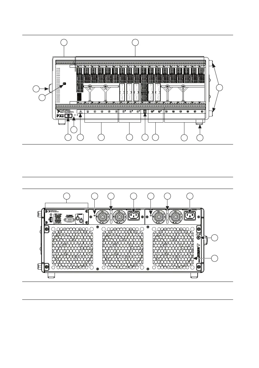
Figure 1-1. Front View of the PXIe-1095 Chassis
Figure 1-2. Rear View of the PXIe-1095 Chassis
1 System Controller Expansion Slot
2 Backplane Connectors
3 Removable Feet
4 PXI Express Peripheral Slots (11x)
5 PXI Express Hybrid Peripheral Slots (5x)
6 PXI Express System Timing Slot
7 PXI Express System Controller Slot
8 Front Panel LEDs
9 Power Inhibit Switch
10 DIP Switch
11 Chassis Carry Handle
1 Timing and Synchronization Upgrade
2 Rear Panel Power Supply LED
3 Power Supply
4 Universal AC Input
5 Chassis Protective Earth Terminal
6 Fan Module
PS TEMP
PXIe-1095
2
3
6
5
5
4
4
7
8
1
3
9
10
11
1 3 4 3 42 2
6
5

 Loading...