© National Instruments | 2-11
PXIe-1095 User Manual
Each power supply has a single LED that indicates the health of that supply. Table 2-2 describes
the rear panel LED states. Refer to Figure 1-2, Rear View of the PXIe-1095 Chassis for LED
location.
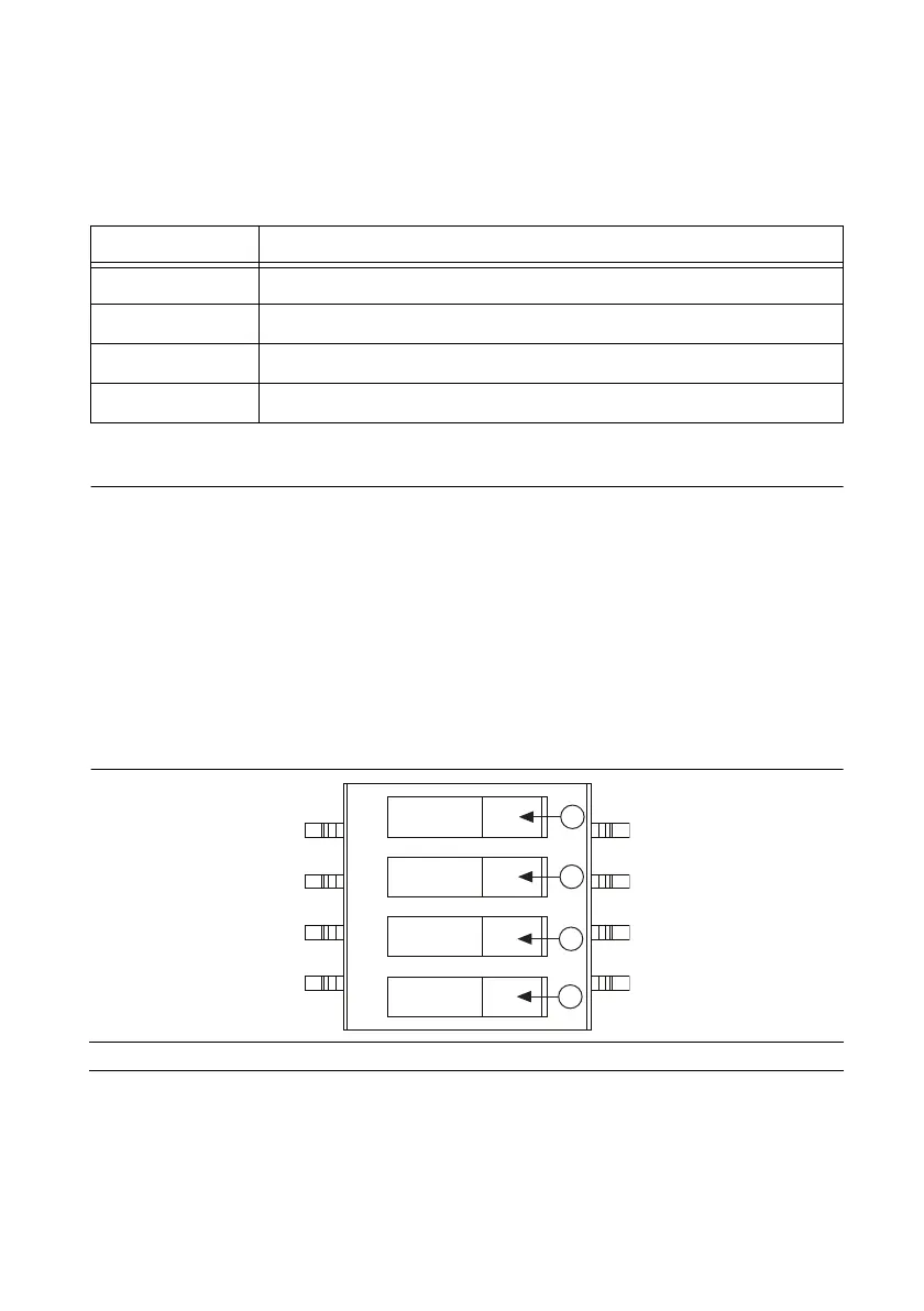
DIP Switches
The backplane has a DIP switch that may be used to control chassis behavior. Refer to
Figure 1-1, Front View of the PXIe-1095 Chassis for the backplane DIP switch location.
DIP switch #1 (first from the bottom) controls the chassis fan mode. When this switch is in the
off (right) position, Auto mode is selected. When this switch is in the on (left) position,
High mode is selected.
DIP switch #2 (second from the bottom) controls the chassis Inhibit Mode. When this switch is
in the off (right) position, Default mode is selected. When this switch is in the on (left) position,
Manual mode is selected.
Figure 2-7. Backplane DIP Switches
Table 2-2. Rear Power Supply LED States
State Description
Off Power supply is unplugged or in standby.
Steady green Main power is active and supply is operating normally.
Blinking red Power supply is operating outside of specification.
Steady red Power supply has failed.
1 Switch #1 (Fan) 2 Switch #2 (PWR) 3 Switch #3 (NC) Switch #4 (NC)

 Loading...