1-8 | ni.com
Chapter 1 Getting Started
System Timing Slot
The System Timing Slot is slot 10. The system timing slot will accept the following peripheral
modules:
• A PXI Express System Timing Module with x8, x4, or x1 PCI Express link to the system
slot through a PCI Express switch. Each PXI Express peripheral or hybrid peripheral slot
can link up to a Gen-3 x8 PCI Express, providing a maximum nominal single-direction
bandwidth of 8 GB/s.
• A PXI Express Peripheral with x8, x4, or x1 PCI Express link to the system slot through a
PCI Express switch.
• A CompactPCI Express Type-2 Peripheral with x8, x4, or x1 PCI Express link to the system
slot through a PCI Express switch.
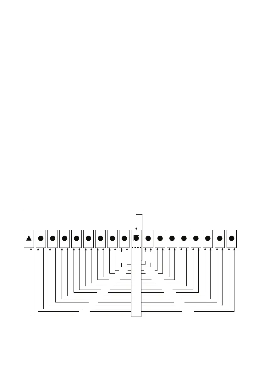
The system timing slot has 3 dedicated differential pairs (PXIe_DSTAR) connected from the
TP1 and TP2 connectors to the XP3 connector for each PXI Express peripheral or hybrid
peripheral slot, as well as routed back to the XP3 connector of the system timing slot as shown
in Figure 1-4. The PXIe_DSTAR pairs can be used for high-speed triggering, synchronization
and clocking. Refer to the PXI Express Specification for details.
The system timing slot also has a single-ended (PXI Star) trigger connected to every slot. Refer
to Figure 1-4 for details.
The system timing slot has a pin (PXI_CLK10_IN) through which a system timing module may
source a 10 MHz clock to which the backplane will phase-lock. Refer to the System Reference
Clock section for details.
Figure 1-4. PXI Express Star Connectivity Diagram
1 2 3 4 5 6 7
H
8
H
9
H
10
11
H
12
H
13 14 15 16 17 18
DSTAR 6
DSTAR 5
DSTAR 7
DSTAR 4
DSTAR 3
DSTAR 2
DSTAR 1
DSTAR 15
DSTAR 14
DSTAR 13
DSTAR 16
DSTAR 12
DSTAR 11
DSTAR 10
STAR 7
STAR 8
STAR 6
STAR 5
STAR 4
STAR 3
STAR 2
STAR
1
STAR 10
STAR 11
STAR 12
STAR 13
STAR 14
STAR 15
STAR 16
DSTA
R 8
DSTAR 9
DSTAR 0
ST
AR 9
ST
AR 0

 Loading...