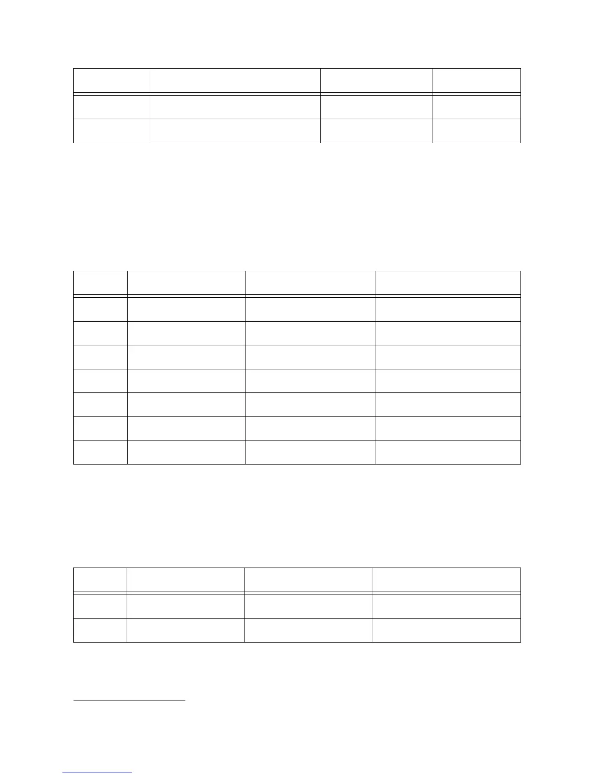
Table 8. SKiiP 4 Connector CAN Configuration (Continued)
Inverter Inverter Connector CAN Switch Contacts
5 J21 SW20 1, 2
6 J22 SW22 1, 2
Inverter Analog Output Configuration
SKiiP 3 GB inverters come in two variants: one with temperature output, another with voltage
output on pin 12. The return for all analog signals is on pin 13. The interface board can be
configured so that the signals are routed to the correct GPIC analog inputs. You can configure
the signals by populating resistors on the sbRIO-9687. The options are listed below.
Table 9. SKiiP 3 Connector Output Type Selection
Inverter Inverter Connector Temperature Output
3
DC Link Voltage Output
0 J36 R865 R859
1 J37 R860 R852
2 J38 R861 R854
3 J39 R862 R855
4 J40 R863 R856
5 J41 R864 R858
6 J42 R818 R817
SKiiP 3 GD inverters do not have separate return paths for DC link voltage and temperature
analog outputs. For accurate measurements, the returns for the signal that is used in the system
should be connected to ground with the onboard switch. If both temperature and DC link
voltage are used, close both circuits on the corresponding switch. The options are listed below.
Table 10. SKiiP 3 GD Connector Signal Ground Connections
Inverter Inverter Connector Temperature Ground DC Link Voltage Ground
0 J26 SW51 contact 1 SW52 contact 1
1 J27 SW51 contact 2 SW52 contact 2
3
Temperature output is populated by default.
sbRIO-9687 User Manual | © National Instruments | 13

 Loading...


