Inverter Signals
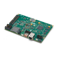
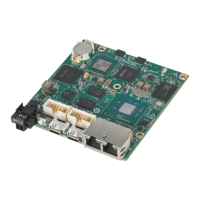
One of the main functions of the sbRIO-9687 is to provide an interface between the
sbRIO-9683 or sbRIO-9684 GPIC controller and up to seven single-phase Semikron inverters.
The following tables show the connections between inverter signals and the GPIC. Only one
connector from each column of the following tables can be used at a time. Using two
connectors from one column could result in unpredictable behavior or damage to the interface
board or inverters.
Table 3. Signal Assignments, GPIC to SKiiP 4 (Single-Phase Inverter)
Signal Inv. 0
(J16)
Inv. 1
(J17)
Inv. 2
(J18)
Inv. 3
(J19)
Inv. 4
(J20)
Inv. 5
(J21)
Inv. 6
(J22)
High Side
IGBT
DO1 DO3 DO5 DO7 DO9 DO11 DO13
Low Side
IGBT
DO0 DO2 DO4 DO6 DO8 DO10 DO12
Current
Sensor
AI0± AI1± AI2± AI3± AI4± AI5± AI6±
DC Link
Voltage
AI7±
or AI_0
AI8±
or AI_1
AI9±
or AI_2
AI10±
or AI_3
AI11±
or AI_4
AI12±
or AI_5
AI13±
or AI_6
Temperature
Sensor
AI_0 AI_1 AI_2 AI_3 AI_4 AI_5 AI_6
HALT DO_0,
DI_P0.0
DO_1,
DI_P0.1
DO_2,
DI_P0.2
DO_3,
DI_P0.3
DO_4,
DI_P0.4
DO_5,
DI_P0.5
DO_6,
DI_P0.6
GPIO DI_P0.7 DI_P0.8 DI_P0.9 DI_P0.10 DI_P0.11 DI_P0.12 DI_P0.13
Table 4. Signal Assignments, GPIC to SKiiP 3 GB (Single-Phase Inverter)
Signal Inv. 0
(J36)
Inv. 1
(J37)
Inv. 2
(J38)
Inv. 3
(J39)
Inv. 4
(J40)
Inv. 5
(J41)
Inv. 6
(J42)
High Side
IGBT
DO1 DO3 DO5 DO7 DO9 DO11 DO13
Low Side
IGBT
DO0 DO2 DO4 DO6 DO8 DO10 DO12
sbRIO-9687 User Manual | © National Instruments | 9
 Loading...
