Expansion Board Power
The expansion board connectors have pins for +3.3 V and a +5 V power.
The +3.3 V is supplied directly by the GPIC, and the power is provided at the same time as the
sbRIO-9607 FPGA power. The current on the +3.3 V rail should not exceed 330 mA. For
details, refer to the NI sbRIO-9607 Specifications.
The +5 V pin is connected to the sbRIO-9687 internal rail and can supply up to 1 A for both
connectors.
Note A short circuit on the +5 V rail could shut down the sbRIO-9687 and may
require cycling the +24 V input.
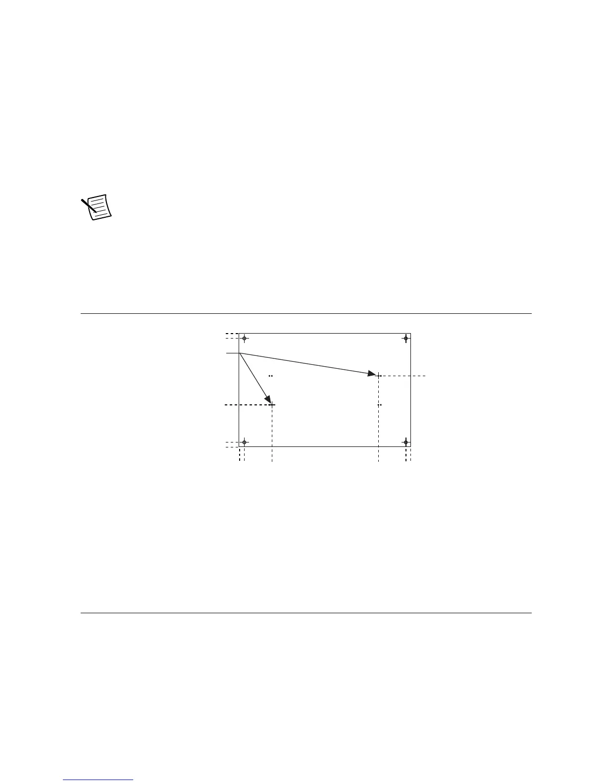
Expansion Board Dimensions
An expansion board must have two mating connectors on the secondary side, each with pin 1
located as shown in the following figure.
Figure 20. Expansion Board Dimensions
Feedback Input
The sbRIO-9687 interface board includes two connectors for feedback signals. Each connector
has six RS485 digital inputs for quadrature encoders, named Feedback_x.x_x, and three
inputs for open collector Hall sensors, named Hall_x.x.
Feedback Connectors
The following tables provide pinout information for the J6 and J10 feedback connectors.
42 | ni.com | sbRIO-9687 User Manual

 Loading...


