Power Input
The sbRIO-9687 interface board must be powered with a +24 V DC supply. The power supply
should have a maximum output current higher than the current consumption of the interface
board and all attached inverters. Refer to the sbRIO-9687 Specifications for maximum current
consumption.
The sbRIO-9687 power input is protected against reverse polarity, and it uses a 10 A fuse to
provide protection for overcurrent. Littlefuse Series 314 is recommended, but any compatible
fuse can be used. Refer to the sbRIO-9687 Specifications for maximum fuse rating.
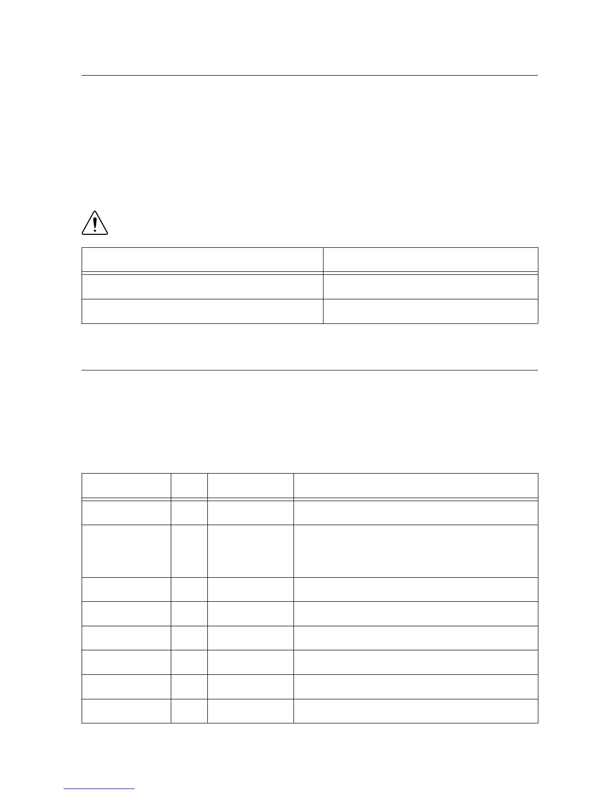
Caution Disconnect the main +24 V supply before replacing the fuse.
Connector Pin Signal Name
1 GND
2 +24 V
GPIC Signals
The main function of the sbRIO-9687 is to provide an interface between the GPIC controller
and different Semikron inverters. The GPIC controller utilizes the following signals. Refer to
the sbRIO-9683 or sbRIO-9684 documentation for connector pinouts and detailed signal
descriptions.
Table 2. GPIC Signals
Generic Name Lines Signal Name Description
Half-Bridge DO 14 DO<0…13> High voltage digital signals for inverter control.
Sourcing DI 28 DI_P0.<0…13>
DI_P1.<0…13>
High voltage digital input with pull-up resistors.
Sinking DO 24 DO_<0…22 > Open collector digital outputs.
Simultaneous AI 16×2 AI<0…15>± Simultaneous sampled differential analog inputs.
Scanned AI 8 AI_<0…7> Scanned analog inputs 0 V to 5 V.
Analog Output 8 AO<0…7> Analog outputs 0 V to 5 V.
LVTTL 32 DIO<0…31> Low voltage TTL lines.
Relay Control 4×2 DO<0…3>± Relay control lines.
8 | ni.com | sbRIO-9687 User Manual

 Loading...


