Note Scanned analog inputs connected to inverters should be set to unipolar mode.
Analog Output
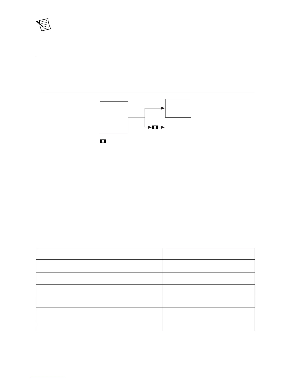
The analog outputs of the GPIC are connected directly to the breakout connector. See Scanned
Analog Input Connectors on page 24 for details. The following figure shows a block diagram
for analog output subsystem.
Figure 13. Analog Output Block Diagram
Analog output can be used on the sbRIO-9687 to set over-range thresholds. See Over-Range
Comparators on page 28 for details about onboard functionality.
The analog output lines have the same specifications as the AO lines of the GPIC. For more
information, refer to NI 9683 User Manual and Specifications and NI 9684 User Manual and
Specifications.
Analog Output Configuration
Analog outputs can be disconnected from the onboard functionality by changing the
corresponding DIP switch to the OFF position. Refer to the following table for information
about analog output configuration.
Table 22. Analog Output Configuration
GPIC Analog Output SW21 Contact

 Loading...


