Table 27. Sourcing Digital Input Signals (Continued)
GPIC DI Signal Onboard Function Disconnecting Resistor
DI_P0.3 HALT3 R535
DI_P0.4 HALT4 R516
DI_P0.5 HALT5 R633
DI_P0.6 HALT6 R566
DI_P0.7 GPIO0 R500
DI_P0.8 GPIO1 R501
DI_P0.9 GPIO2 R497
DI_P0.10 GPIO3 R498
DI_P0.11 GPIO4 R572
DI_P0.12 GPIO5 R499
DI_P0.13 GPIO6 R573
Sinking Digital Output
The GPIC has 24 sinking digital outputs. Each sinking DO is connected to the breakout
connector. The sbRIO-9687 interface board uses some of the DO lines, which can be
disconnected from sbRIO-9687 circuitry by depopulating 0 Ω resistors.
The sinking DO lines have the same electrical specifications as the DO lines of the GPIC. For
more information, refer to the NI 9683 User Manual and Specifications or the NI 9684 User
Manual and Specifications. The GPIC has current sinking digital outputs, which means that
the output pin is driven to ground (GND) when the channel is ON.
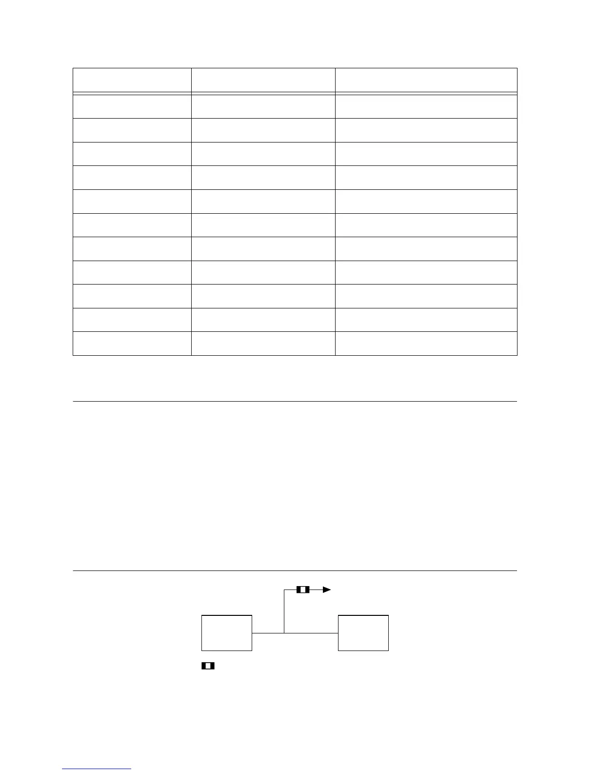
The following figure is a block diagram of the sinking digital output.
Figure 16. Sinking Digital Output Block Diagram

 Loading...


