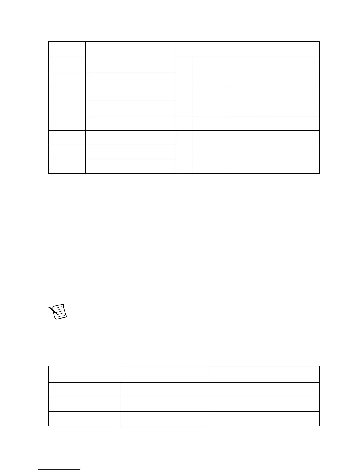
11 DI_P1.2 29 DI_P1.3
12 DI_P1.4 30 DI_P1.5
13 DI_P1.6 31 DI_P1.7
14 DI_P1.8 32 DI_P1.9
15 DI_P1.10 33 DI_P1.11
16 DI_P1.12 34 DI_P1.13
17 GND 35 VI_P1
18 Not Connected 36 Not Connected
Sourcing Digital Input Configuration
Port 0 of the sourcing digital input is powered at +24 V through the sbRIO-9687 interface
board. This power is available at the DI connector on pins 9 and 27. The +24 V can be used to
power external circuits or port 1.
Port 1 is not powered from sbRIO-9687 interface board; it should be powered externally at a
voltage that matches the voltage levels of the application. Power for port 1 is connected at pins
18 and 36 of J12 connector.
Port 0 DI lines are used on the sbRIO-9687 interface board. For details, refer to Halt Signals
on page 36 and GPIO Signals on page 37. If Port 0 DI lines are not used for the application,
they can be disconnected from onboard functionality by depopulating the corresponding
resistor.
Note If port 0 sinking DI lines are used outside the sbRIO-9687, they should be
disconnected from onboard functionality.
The following table provides information about the onboard function and corresponding
resistor for sourcing DI signals.
Table 27. Sourcing Digital Input Signals
GPIC DI Signal Onboard Function Disconnecting Resistor

 Loading...


