Table 39. LED Command Lines
LED Reference Indicator LED Color LVTTL Command Line
DS1 RED DIO31
DS2 GREEN DIO30
DS3 GREEN DIO29
DS4 GREEN Always On
Thermistor
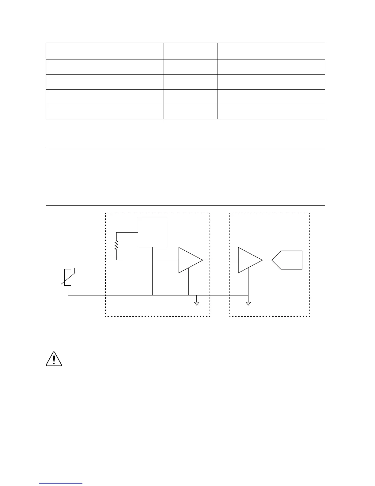
The sbRIO-9687 has support for two 10 kΩ thermistors for temperature measurement. The
sensors are connected to a 2.5 V reference through a 10 kΩ precision resistor. The thermistor
voltage is amplified by a factor of 2 on a gain stage, and then directed to the GPIC scanned
analog inputs.
Figure 21. Thermistor Measurement Circuit
ADCx2
sbRIO-9687 sbRIO-9683/9684
GAIN
Differential
Amplifier
scAI
GNDGND
Therm
Thermistor
10kΩ
2.5V
Reference
The thermistors should be connected between the two available terminals, Therm and
Therm_GND.
Caution Do not electrically connect the thermistor body to the chassis ground or to
high voltage lines in the cabinet. Such a connection could permanently damage the
sbRIO-9687.
Thermistor Connector
The following table provides pinout information for the thermistor connector. If a shielded
cable is used for the thermistor, connect the shield to the CHASSIS GND pins.
sbRIO-9687 User Manual | © National Instruments | 45

 Loading...


