Table 33. Mapping Between GPIO Signals and Sinking Digital Input (Continued)
GPIO Line (Inverters) DI Line (GPIC)
GPIO4 DI_P0.11
GPIO5 DI_P0.12
GPIO6 DI_P0.13
LVTTL Lines
The sbRIO-9683 or sbRIO-9684 GPIC has 32 LVTTL digital signals. These signals are high
speed bidirectional lines with 3.3 V logical levels. All LVTTL lines are used for onboard
functions on the sbRIO-9687. All LVTTL signals are available at the two expansion board
connectors. The LVTTL signals are connected directly to the expansion board connectors and
have 0 Ω resistors to onboard functions.
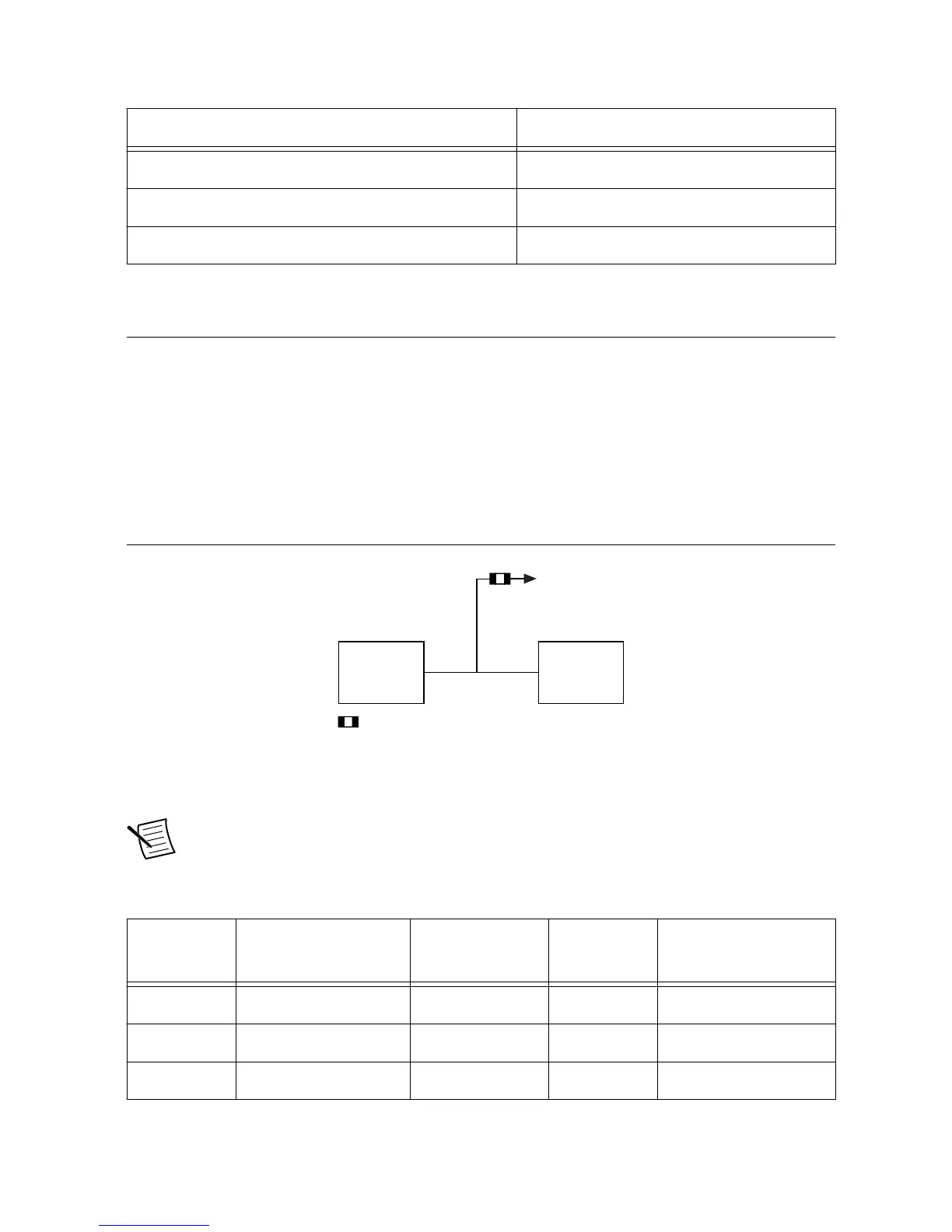
The following figure shows a block diagram for the LVTTL lines.
Figure 19. LVTTL Lines Block Diagram
GPIC
LVTTL
Extension
Connector
Onboard
Functionality
Connector
Configurable position
The following table provides information about the onboard function and corresponding
resistor for the LVTTL lines.
Note It is highly recommended to disconnect the LVTTL signals from sbRIO-9687
functionality when they are being used with an expansion board.
Table 34. LVTTL Lines
GPIC Signal Onboard Function Direction (to
GPIC)
Active State Disconnecting
Resistor
DIO0 Over Range 0 Input Low R165
DIO1 Over Range 1 Input Low R156
DIO2 Over Range 2 Input Low R155
38 | ni.com | sbRIO-9687 User Manual

 Loading...


