Sinking DO Connector
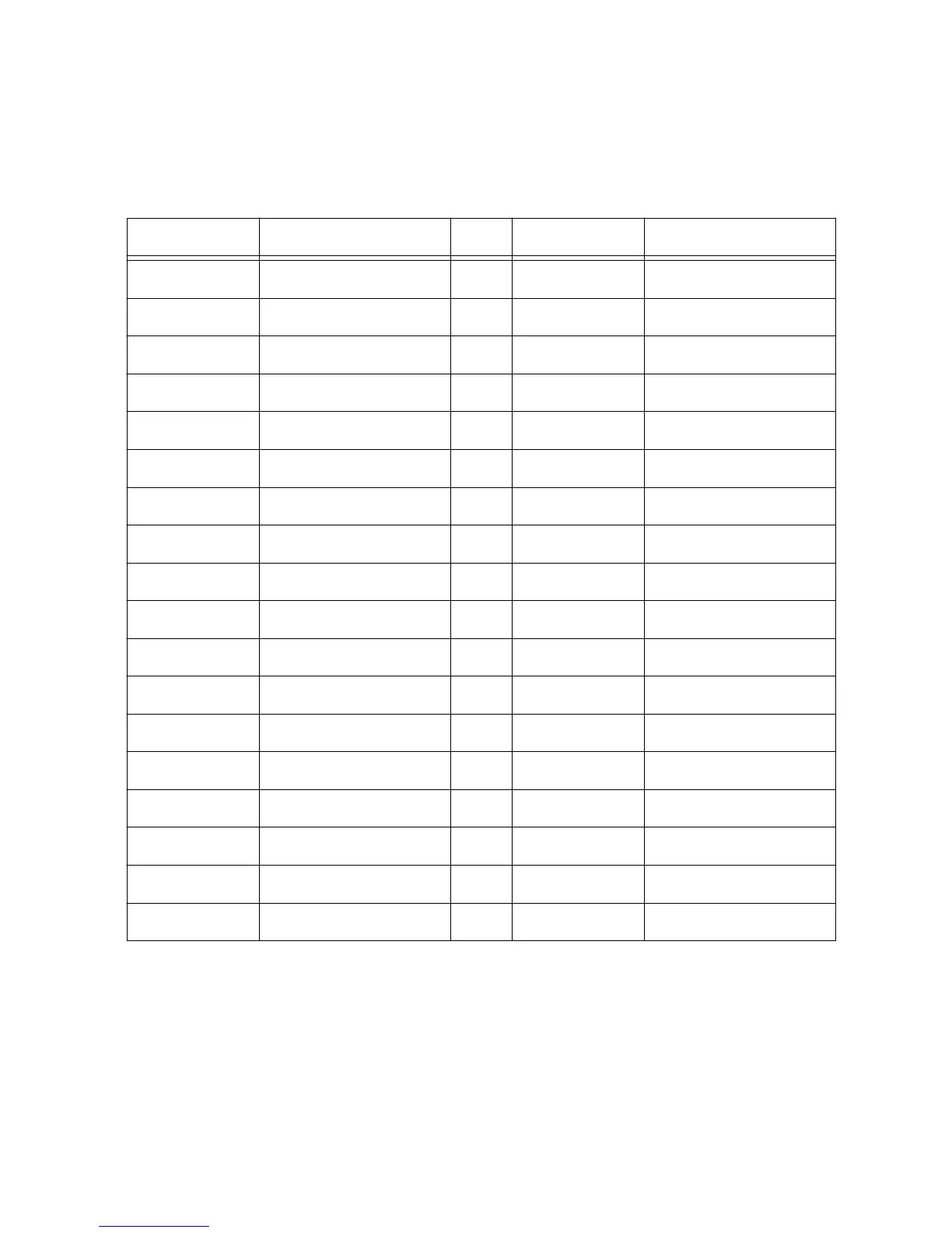
Sinking digital outputs are available at breakout connector J9. The following table contains
pinout information for the sinking DO connector.
Table 28. J9 Sinking Digital Output Pinout
Pin Signal Pin Signal
1 GND 19 GND
2 DO_0 20 DO_1
3 DO_2 21 DO_3
4 DO_4 22 DO_5
5 DO_6 23 DO_7
6 DO_8 24 DO_9
7 DO_10 25 DO_11
8 DO_12 26 DO_13
9 — 27 —
10 GND 28 GND
11 DO_14 29 DO_15
12 DO_16 30 DO_17
13 DO_18 31 DO_19
14 DO_20 32 DO_21
15 DO_22 33 DO_23
16 GND 34 GND
17 GND 35 GND
18 — 36 —
Sinking Digital Output Configuration
The first seven digital output lines are used on the sbRIO-9687 interface board for inverter
signals. See Inverter Digital Signals on page 35 for more details. If sinking digital outputs
need to be used externally, they can be disconnected from onboard functionality by
depopulating the corresponding resistors. The following table provides information about the
onboard function and corresponding resistor for sinking DO signals.
34 | ni.com | sbRIO-9687 User Manual

 Loading...


