AO6 7
AO7 8
Note Analog outputs that are used outside the sbRIO-9687 should be disconnected
from onboard functionality.
Over-Range Comparators
The sbRIO-9687 interface board has eight over-range comparators that can be connected to
analog input signals. The over-range comparators are triggered if the absolute value of the
input is over the set voltage. For example, if the threshold is set at 7 V, then the over range is
triggered if the input is over 7 V or under -7 V.
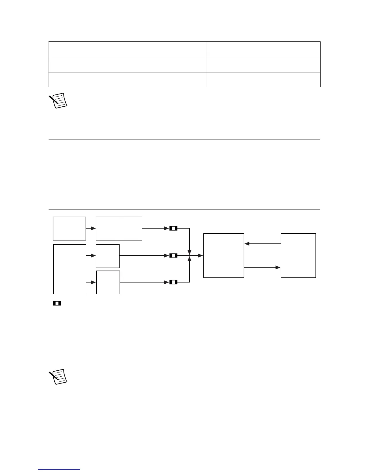
The following figure is a block diagram for the over-range circuits.
Figure 14. Over-Range Circuit Block Diagram
The eight over-range comparators can be connected to inverter phase current, inverter DC link
voltage, or to one of the 16 simultaneous sampled analog inputs. The over-range threshold can
be set using one of the GPIC analog outputs or by populating a resistor divider on the board.
The over-range output is an active low digital signal connected to the GPIC low voltage TTL
inputs.
Note If any of the DIO lines (DIO0 to DIO7) are to be used for the extension
board, they should be disconnected from the onboard functionality by depopulating
the corresponding 0 Ω resistor. See LVTTL Lines on page 38 for details.
Over-Range Comparator Input Configuration
Over-range comparators are connected to the input source with a series of DIP switches.
Because all input signals are differential, a pair of contacts should be closed to select one
28 | ni.com | sbRIO-9687 User Manual

 Loading...


