corresponding AO channel to the appropriate DC value. The comparator threshold is twice the
set AO voltage and acts for both positive and negative input voltages.
V
AO
=
V
tℎresℎold
2
Note If GPIC analog outputs are used for the over-range comparator set point, the
corresponding contact on switch SW21 should be turned ON.
If using the onboard resistors to set the over-range threshold, the analog outputs should be
disconnected from the onboard functionality. See Analog Output Configuration on page 27 for
configuration information. The set point is established by populating the corresponding
resistor for each channel. To calculate the resistor value, use the following formula:
R
tℎresℎold
=
V
tℎresℎold
10V − V
tℎresℎold
× 100kΩ
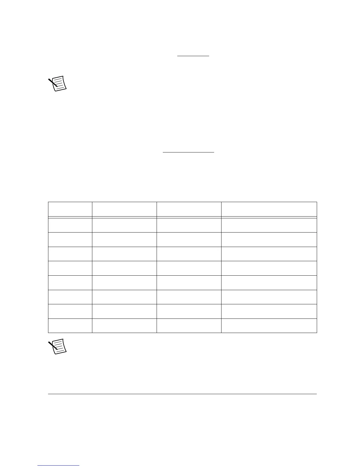
The following table provides threshold settings for the sbRIO-9687 over-range comparators.
Table 25. Over-Range Comparator Threshold Setting
Circuit Set Point 1 Set Point 2 Over-Range OUT
O-Ra 0 AO0 R381 DIO0
O-Ra 1 AO1 R383 DIO1
O-Ra 2 AO2 R373 DIO2
O-Ra 3 AO3 R386 DIO3
O-Ra 4 AO4 R394 DIO4
O-Ra 5 AO5 R396 DIO5
O-Ra 6 AO6 R403 DIO6
O-Ra 7 AO7 R244 DIO7
Note If any of the lines DIO0 to DIO7 are to be used for the extension board, they
should be disconnected from the onboard functionality by depopulating the
corresponding 0 Ω resistor. See LVTTL Lines on page 38 for details.
Sourcing Digital Input
The GPIC has 28 sourcing digital inputs grouped in two ports. Each of the sourcing digital
inputs is connected to a breakout connector on the sbRIO-9687 interface board. The DI lines
30 | ni.com | sbRIO-9687 User Manual

 Loading...


