AI_0 UDC 0 SW30 1, 2 Temp0 SW30 3, 4 scAI0 SW30 5, 6
AI_1 UDC 1 SW26 1, 2 Temp1 SW26 3, 4 scAI1 SW26 5, 6
AI_2 UDC 2 SW27 1, 2 Temp2 SW27 3, 4 scAI2 SW27 5, 6
AI_3 UDC 3 SW28 1, 2 Temp3 SW28 3, 4 scAI3 SW28 5, 6
AI_4 UDC 4 SW29 1, 2 Temp4 SW29 3, 4 scAI4 SW29 5, 6
AI_5 UDC 5 SW31 1, 2 Temp5 SW31 3, 4 scAI5 SW31 5, 6
AI_6 UDC 6 SW23 1, 2 Temp6 SW23 3, 4 scAI6 SW23 5, 6
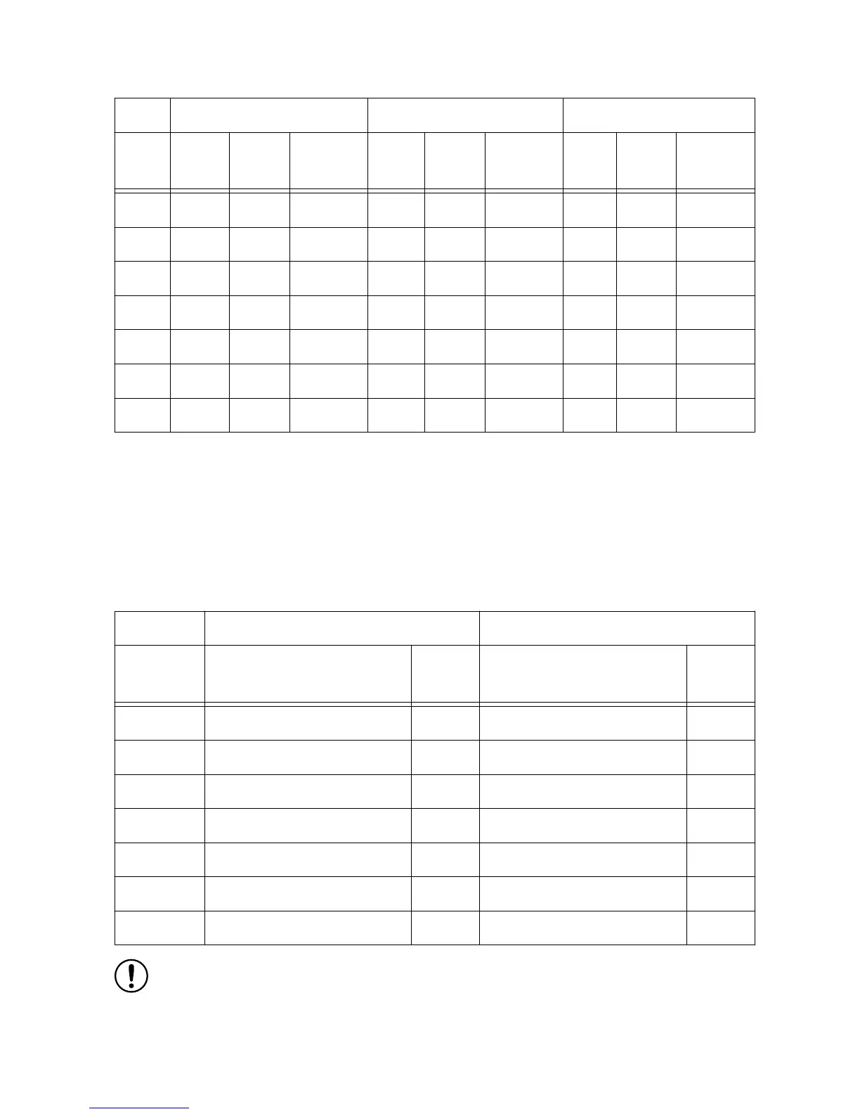
Unipolar/Bipolar Mode Configuration
Each scanned analog input can be configured to accept unipolar or bipolar input voltages.
Refer to the sbRIO-9687 Specifications for details about the input range and accuracy for each
setting. Refer to the following table for information about configuring unipolar and bipolar
input voltages.
Table 21. Scanned Analog Input Unipolar/Bipolar Configuration
Unipolar Input (0 V to 10 V) Bipolar Input (-5 V to 5 V)
GPIC Input Switch Reference
Designator
Contact Switch Reference
Designator
Contact
AI0 SW12 1 SW12 2
AI1 SW12 3 SW12 4
AI2 SW11 1 SW11 2
AI3 SW11 3 SW11 4
AI4 SW13 1 SW13 2
AI5 SW13 3 SW13 4
AI6 SW14 1 SW14 2
Notice Only one configuration should be selected for each scanned analog input.
Selecting both unipolar/bipolar configuration at the same time will produce
unexpected results.
26 | ni.com | sbRIO-9687 User Manual

 Loading...


