Appendix A Device-Specific Information
© National Instruments Corporation A-15 NI USB-621x User Manual
Note For more information about default NI-DAQmx counter inputs, refer to Connecting
Counter Signals in the NI-DAQmx Help or the LabVIEW Help in version 8.0 or later.
Connecting Signals to the USB-6212/6216 BNC
Analog Input
You can use each analog input BNC connector for one signal in differential
mode or two signals in single-ended mode:
• Differential Mode—To connect signals in differential mode,
determine the type of signal source you are using—a floating signal
(FS) source or a ground-referenced signal (GS) source. Refer to the
Connecting Analog Input Sig
nals on USB-6210/6211/6212 Devices or
Connecting Analog Input Signals on USB-6215/6216/6218 Devices
section o
f Chapter 4, Analog Input, for more information.
To measure a floating signal source, move the switch to the FS position.
To measure a ground-referenced signal source, move the switch to the
GS position. Figure A-6 shows the AI 0 BNC and corresponding FS/GS
switch on the top panel of the USB-6212/6216 BNC.
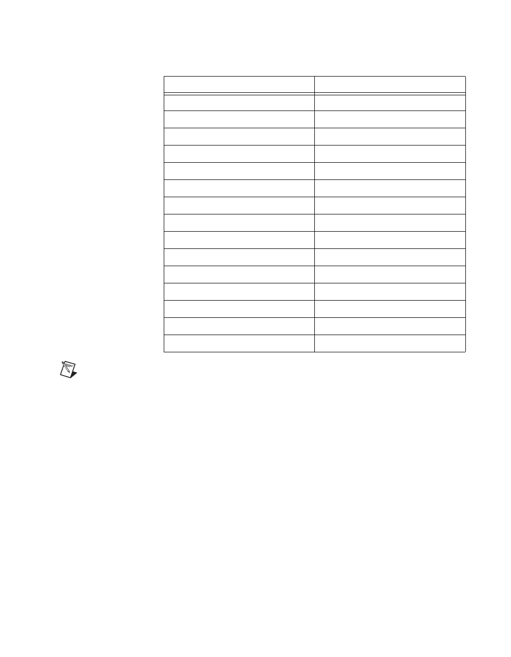
Table A-5. Default NI-DAQmx Counter/Timer Pins
Counter/Timer Signal Default Terminal Name
CTR 0 SRC PFI 8
CTR 0 GATE PFI 9
CTR 0 AUX PFI 10
CTR 0 OUT PFI 12
CTR 0 A PFI 8
CTR 0 Z PFI 9
CTR 0 B PFI 10
CTR 1 SRC PFI 3
CTR 1 GATE PFI 4
CTR 1 AUX PFI 11
CTR 1 OUT PFI 13
CTR 1 A PFI 3
CTR 1 Z PFI 4
CTR 1 B PFI 11
FREQ OUT PFI 14

 Loading...


