Appendix A Device-Specific Information
NI USB-621x User Manual A-16 ni.com
Figure A-6. FS/GS Switch
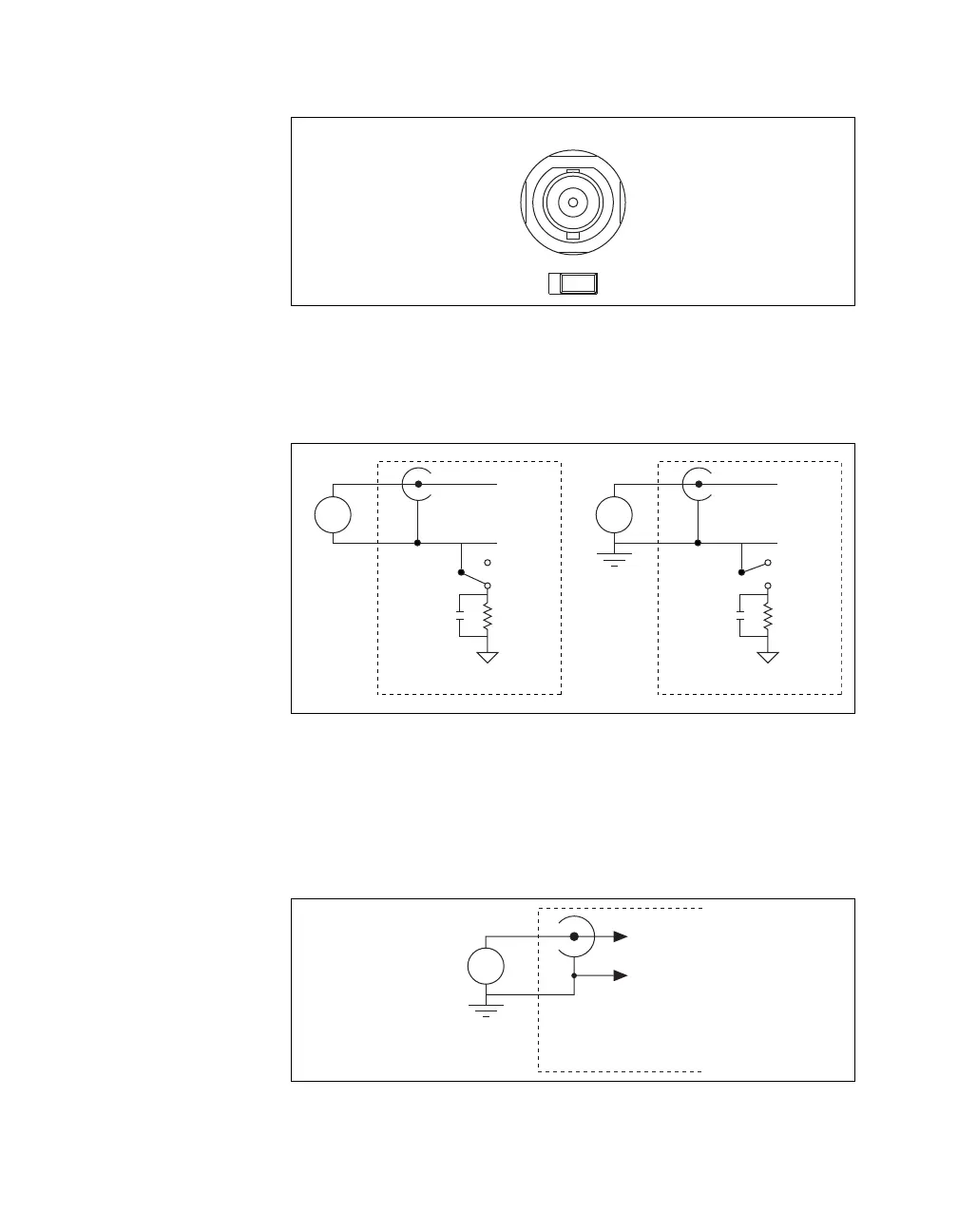
Figure A-7 shows the analog input circuitry on the USB-6212/6216
BNC. When the switch is set to the FS position, AI x – is grounded
through a 0.1 μF capacitor in parallel with a 5 kΩ resistor.
Figure A-7. Analog Input Circuitry
• Single-Ended Mode—For each BNC connector that you use for two
single-ended channels, set the source type switch to the GS position.
This setting disconnects the built-in ground reference resistor from the
negative terminal of the BNC connector, allowing the connector to be
used as a single-ended channel, as shown in Figure A-8.
Figure A-8. Single-Ended Channels
FS GS
AI 0
AI x +
AI x –
GS
0.1 µF
5 kΩ
AI GND
FS
+
–
USB-621x Device
Floating
Source
AI x +
AI x –
GS
0.1 µF
5 kΩ
AI GND
FS
+
–
USB-621x Device
Ground-
Referenced
Source
AI x
+
–
AI x+8
USB-621x BNC Device
Ground Ref.
Source (GS)

 Loading...


