Appendix A Device-Specific Information
NI USB-621x User Manual A-24 ni.com
Figure A-15. FS/GS Switch
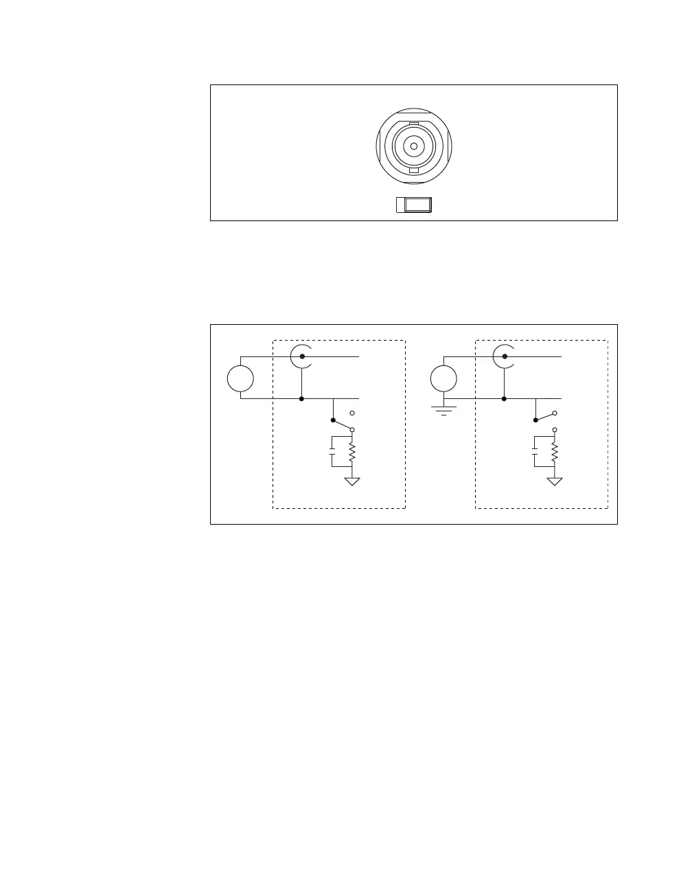
Figure A-16 shows the analog input circuitry on the USB-6218 BNC.
When the switch is set to the FS position, AI x – is grounded through
a 0.1 μF capacitor in parallel with a 5 kΩ resistor.
Figure A-16. Analog Input Circuitry
FS GS
AI 0
AI x +
AI x –
GS
0.1 µF
5 kΩ
AI GND
FS
+
–
USB-621x Device
Floating
Source
AI x +
AI x –
GS
0.1 µF
5 kΩ
AI GND
FS
+
–
USB-621x Device
Ground-
Referenced
Source

 Loading...


