Appendix A Device-Specific Information
NI USB-621x User Manual A-26 ni.com
Refer to the Connecting Analog Output Signals section of Chapter 5,
Analog Output, for more information.
USER
The USER BNC connector allows you to use a BNC connector for a digital
or timing I/O signal of your choice. The USER BNC connector is routed
(internal to the USB-6218 BNC) to the USER screw terminal, as shown in
Figure A-19.
Figure A-19. USER BNC Connection
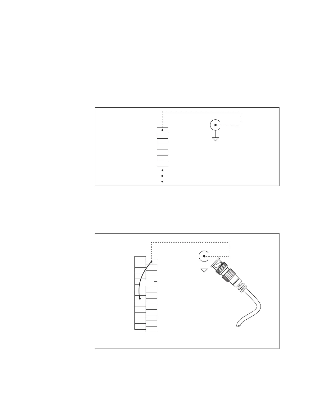
Figure A-20 shows an example of how to use the USER BNC. To access
the PFI 9/P0.5 signal from a BNC, connect USER on the screw terminal
block to PFI 9/P0.5 with a wire.
Figure A-20. Connecting PFI 9/P0.5 to USER BNC
USER
D GND
Px.x
Px.x
Px.x
Px.x
Px.x
Screw
Te r m i nal
Block
USER BNC
D GND
Internal
Connection
BNC Cable
PFI 9
Signal
USER
AI SENSE
AI GND
D GND
P1.7 (OUT)
P1.6 (OUT)
P1.5 (OUT)
P1.4 (OUT)
D GND
P1.3 (OUT)
P1.2 (OUT)
P1.1 (OUT)
P1.0 (OUT)
USER BNC
D GND
Screw
Te r m i nal
Block
Internal
Connection
D GND
D GND
+5 V
D GND
P0.7 (IN)
P0.6 (IN)
P0.5 (IN)
P0.4 (IN)
D GND
P0.3 (IN)
P0.2 (IN)
P0.1 (IN)
P0.0 (IN)
Wire
 Loading...


