Chapter 4 Analog Input
NI USB-621x User Manual 4-4 ni.com
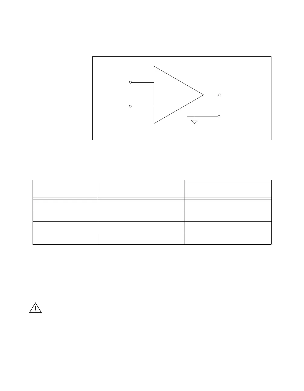
with this amplified voltage. The amount of amplification (the gain) is
determined by the analog input range, as shown in Figure 4-2.
Figure 4-2. NI-PGIA
Table 4-1 shows how signals are routed to the NI-PGIA.
For differential measurements, AI 0 and AI 8 are the positive and negative
inputs of differential analog input channel 0. For a complete list of signal
pairs that form differential input channels, refer to the I/O Connector Signal
Descriptions section of Chapter 3, Connector and LED Information.
AI ground-reference setting is sometimes referred to as AI terminal
configuration.
Caution The maximum input voltages rating of AI signals with respect to AI GND
(and for differential signals with respect to each other) are listed in the NI USB-621x
Specifications. Exceeding the maximum input voltage of AI signals distorts the
measurement results. Exceeding the maximum input voltage rating also can damage the
device and the computer. NI is not liable for any damage resulting from such signal
connections.
Table 4-1. Signals Routed to the NI-PGIA
AI Ground-Reference
Settings
Signals Routed to the Positive
Input of the NI-PGIA (V
in+
)
Signals Routed to the Negative
Input of the NI-PGIA (V
in–
)
RSE AI <0..31> AI GND
NRSE AI <0..31> AI SENSE
DIFF AI <0..7> AI <8..15>
AI <16..23> AI <24..31>
V
in+
V
m
= [V
in+
– V
in–
] × Gain
V
m
V
in–
PGIA
+
–
Measured
Voltage
Instrumentation
Amplifier

 Loading...


