VX150 TO VX2 TROUBLESHOOTING MANUAL RESPONDING TO ALARMS
PAGE 3.1.46 VERSION 2.0 2023-04-20
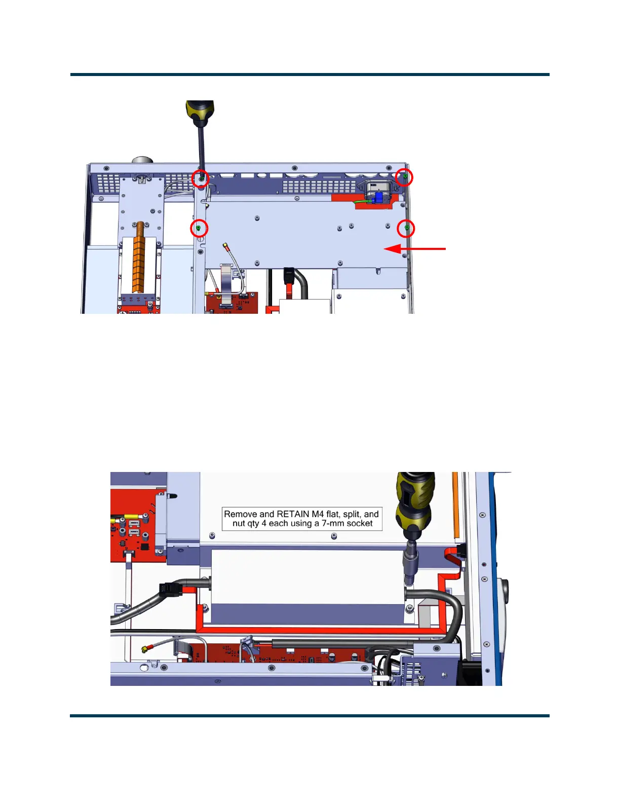
Figure 3.1.11: Exciter/Analog Audio PWB Support Bracket Screws
8. Disconnect wiring from TB1 on the Power Supply Interface PWB (A4, NAPI188*), noting
connections. Cut cable ties securing wiring.
9. Disconnect wiring from TB2 on the System Interface PWB (A3, NAPI187), noting connections. Cut
cable ties securing wiring.
10. Remove and retain the four sets of M4 hardware securing the power supply to the chassis using a
7-mm nut driver. See Figure 3.1.12. Note power supply orientation.
Figure 3.1.12: Power Supply Securing Hardware
Exciter/Analog Audio
PWB Support Bracket
Remove and RETAIN M3 hardware, qty 4 using #1 Phillips