NAVMAN TRACKER 5507/5607 Installation and Operation Manual
64
Black
Yellow
Optional sensors and instruments
Fuel sensors: These optional fuel flow sensors
can be fitted to up to two engines:
• NAVMAN petrol/gasoline sensors (see section
16-6).
Engine types supported:
Outboard carburetted two stroke and EFI
petrol/gasoline engines: 50 hp to 300 hp.
Outboard four stroke petrol/gasoline
engines: 90 hp to 300 hp.
Inboard petrol/gasoline engines: 70 hp to
400 hp.
Flow rate (per engine):
Minimum: 5 litres per hour (1.3 U.S.
gallons per hour).
Maximum: 130 litres per hour (34 U.S.
gallons per hour).
• NAVMAN diesel sensors (see section 16-7)
Flow rate (per engine):
Minimum: 25 litres per hour (6.5 U.S.
gallons per hour).
Maximum: 400 litres per hour (104 U.S.
gallons per hour).
• SmartCraft™ fuel sensors (see section 16-9)
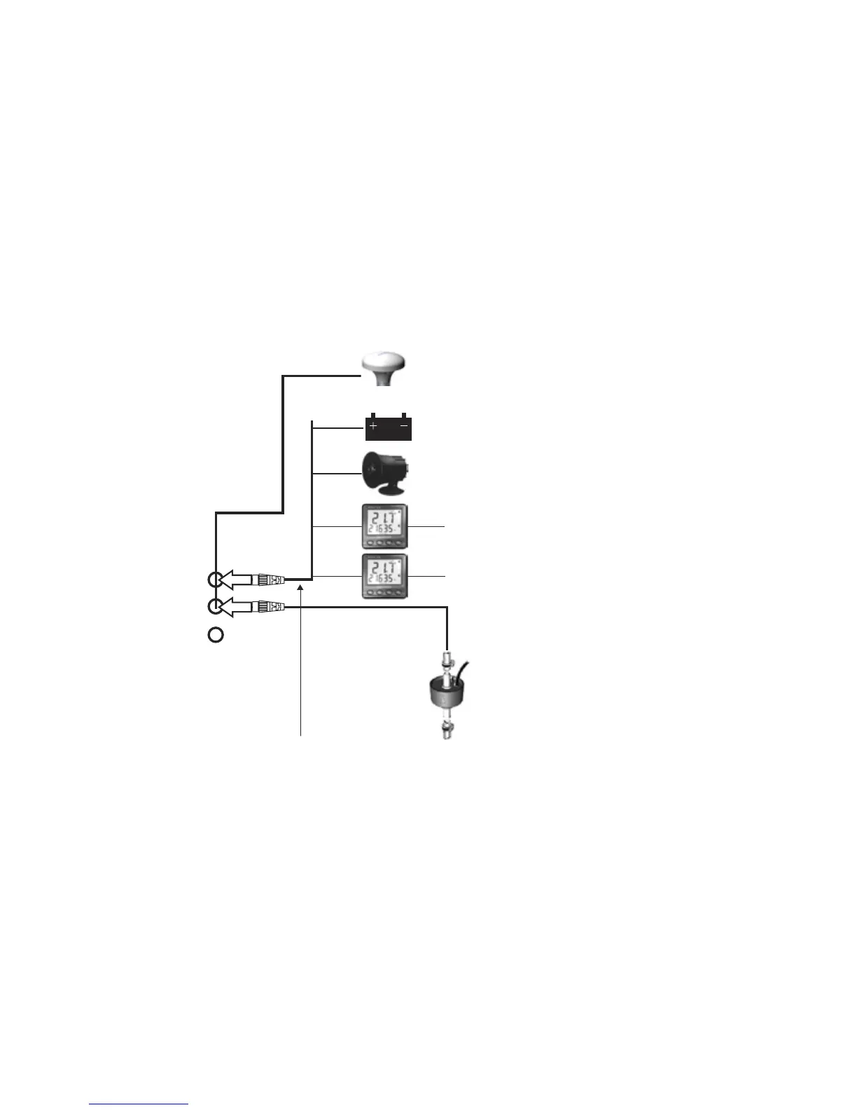
Connections
GPS antenna (16-5)
Power (16-4)
External alarms (16-4)
NavBus instruments (16-10)
NMEA out to instruments (16-11)
Petrol/gasoline sensors (16-6),
NMEA in (16-11), Diesel sensors (16-7)
Display unit
(16-3)
Power/data cable
Pin
Wire Function
1 Black Ground: - power in, NMEA ground. (The cable has two black wires which are
connected inside the cable and it does not matter which black wire you use)
2 Brown Not used
3 White NMEA out
4 Blue NavBus-
5 Red Power in, +10.5 to +30.5 V DC
6 Orange NavBus+
7 Yellow Auto power in
8 Green External alarm out, 30 V DC 200 mA maximum.