NAVMAN TRACKER 5507/5607 Installation and Operation Manual
66
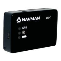
Black
Power/data cable
Red
Yellow
Black
External beepers or
lights
Main switch
12 /24V DC
Fuse 2A
The power/data cable has a black locking collar and flying leads.
1 Wire the 5507/5607 for auto power to have the 5507/5607 turn on with the boat’s ignition switch
or to record engine hours or to record the total fuel used. Otherwise wire for basic power (for more
information, see section 2-3).
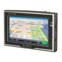
Basic power
Power/data cable
Yellow
Red
Black
Ignition
Ignition switch
Main switch
12/24 V DC
Fuses 2A
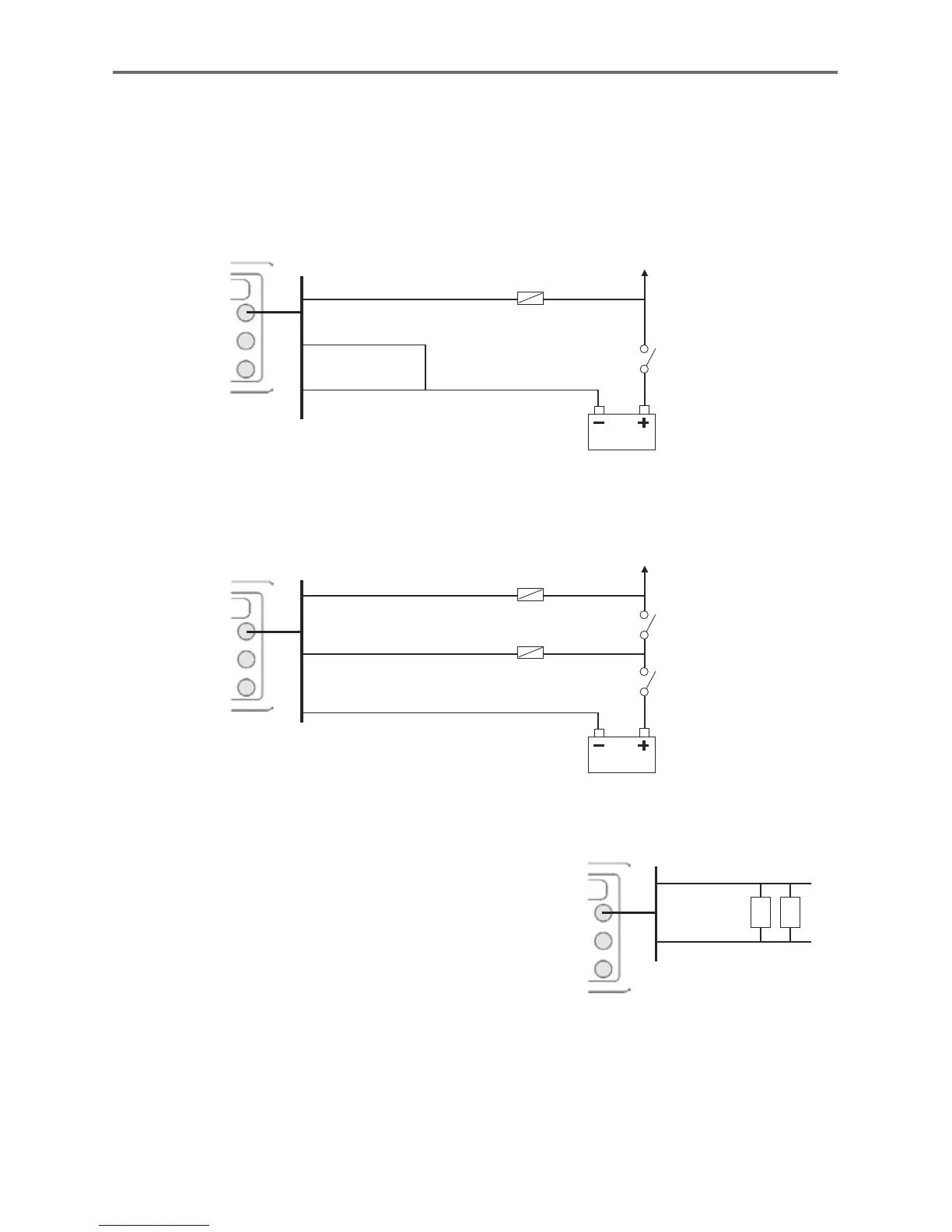
Power/data cable
Red
Green
2 Wire any external alarm beepers or lights.
The alarm output switches to ground to
sound the alarm. If the current is more than
200 mA, fit a relay.
3 Connect the power/data cable to the black
display unit connector; turn the collar to
lock the connector.
Black
Black
16-4 Installation: Power/Data cable
Auto power
During setup, set up Auto power off (see sections 2-2 turning on and off and 14-1 Setup system)