Hardware Installation 2-19
24V USB +Power
The I/O Board provides one latching 24V Powered USB port (Foxconn P/N UB11123-
GHR3-4F or NCR approved equivalent). The 24V Powered USB port is capable of
supplying 24V at 2.3A continuous and 3.0A peak. The color of the connector is red.
The 24V is fused with a resettable fuse (Tyco RUEF250U or NCR approved equivalent).
An overcurrent signal is used to detect when this fuse is open. This signal is connected
to a GPIO on the Super I/O. A separate return line, 24V_RET, is used instead of ground
to provide noise isolation.
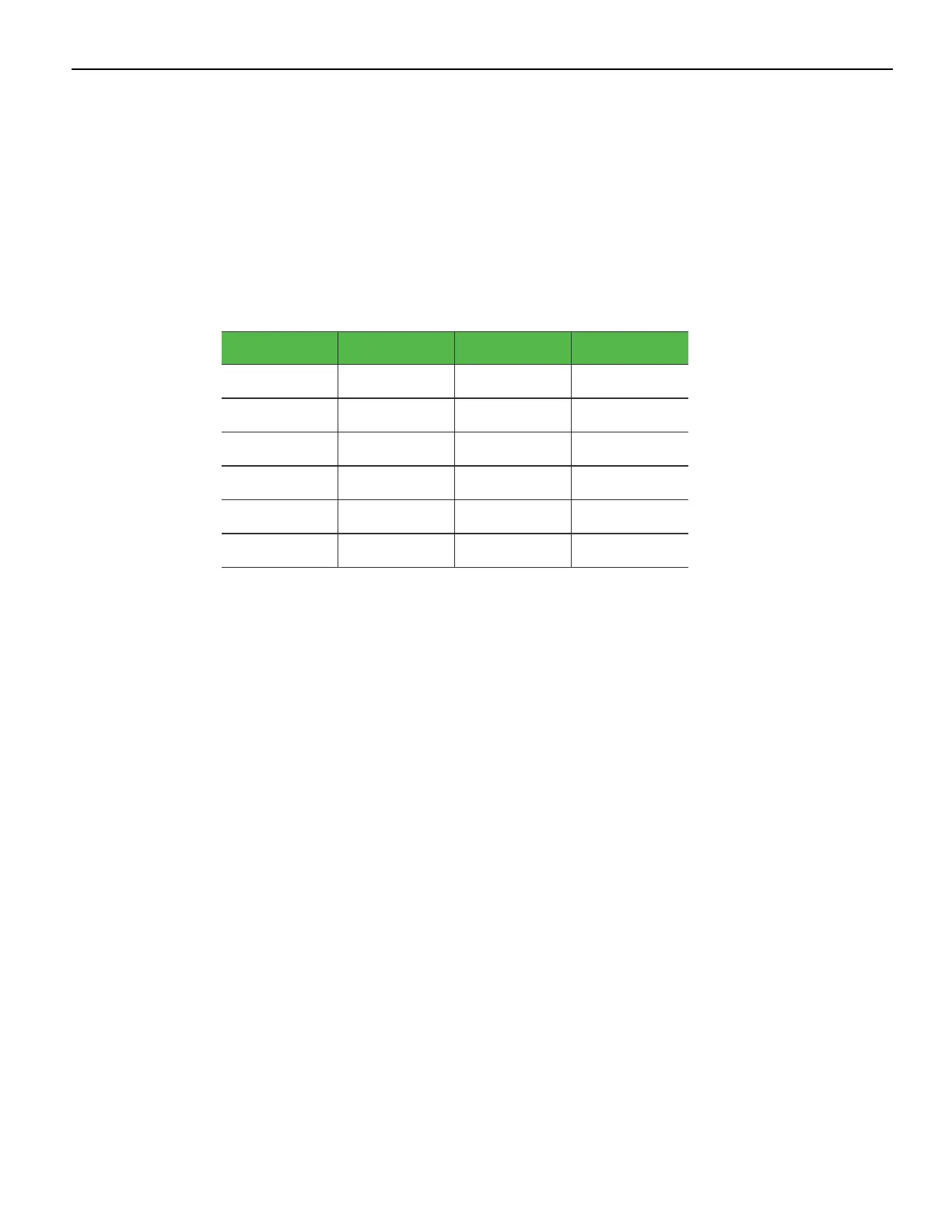
Signal Name Pin Pin Signal Name
USBPWR 1 5 24V_RET
USB D– 2 6 +24V
USBD+ 3 7 +24V
GND 4 8 24V_RET
FRAME GND 9 10 FRAME GND
FRAME GND 11 12 FRAME GND
 Loading...