EasyManua.ls Logo

NCR P1235 - User Manual

NCR P1235
37 pages
Print Icon
To Next Page IconTo Next Page
Loading...
US-IT Restaurant Architecture Team
Installation Guide
NCR P1235 e*SmartClock
Last Updated: 12/6/16
Copyright Notice
The document contains confidential and proprietary information of McDonald’s Corporation. Except with the express prior written permission from
McDonald’s Corporation this document and the information contained herein may not be published, disclosed or used for any other purpose except for that
which it is being provided.

Other manuals for NCR P1235

Questions and Answers

  • T
    tperezAug 9, 2025
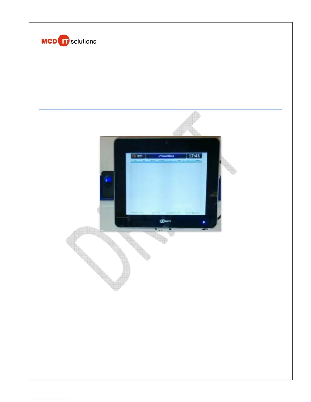
    What to do if the ‘Assign IP address Manually’ screen is shown during staging process on NCR Touch terminals?
    • S
      Shannon SimmonsAug 9, 2025
      If the ‘Assign IP address Manually’ screen appears during the staging process of your NCR Touch terminals, do not enter any values. Ensure the network cable is connected to the POS network switch and that the LED network indicator is flashing green, indicating network connectivity. If there is no green flashing light, reboot the device and check the connectivity again. If the problem persists, Professional Installers should contact their Supplier helpdesk, while OTP Installers should contact their Installation support helpdesk.
  • T
    Terry MurphyAug 16, 2025
    What to do if the biometric reader is not working on NCR P1235?
    • R
      robert53Aug 16, 2025
      If the biometric reader on your NCR Touch terminals is not working, check for a flashing blue light on the device. If the blue LED light is not flashing, the device may be broken. Try rebooting the e*SmartClock and check the biometric device light again. If it still doesn't work, contact the helpdesk.
  • L
    limaryAug 23, 2025
    How to troubleshoot an e*SmartClock device that does not power ON for NCR Touch terminals?
    • S
      sarah34Aug 23, 2025
      If the e*SmartClock device does not power ON, remove the front cable cover to access the I/O ports and ensure the power cord on the left side is properly connected.
  • V
    vgonzalesAug 31, 2025
    Why is a Windows Activation Warning shown on NCR Touch terminals?
    • S
      Sherri MossAug 31, 2025
      This error on NCR Touch terminals should resolve automatically once the Volume License is activated. The Windows license activation does not affect e*SmartClock functionality. Press 'cancel' to dismiss the warning. If the problem persists, Professional Installers should contact their Supplier helpdesk, and OTP Installers should contact their Installation support helpdesk.

Summary

Installation Support and Critical Information

Safety and Installation Precautions

DANGER: Importance of Proper Installation

Emphasizes that safe and satisfactory operation depends on proper installation.

Electrical Code Compliance

Installation must conform to local and national electrical codes.

WARNING: Regulatory Compliance

Installation must comply with all Federal, State, and Local regulations.

e*SmartClock Installation Procedures

7.1 Installation of Network Cable

Step-by-step instructions for determining placement and installing the network cable.

e*SmartClock Bracket Installation

7.2 Installation of e*SmartClock Bracket

Details the process for installing the e*SmartClock bracket on the wall.

e*SmartClock Bracket Mounting Requirements

Details requirements for mounting the e*SmartClock bracket, including wall type and dimensions.

WARNING: Avoid Heat or Moisture Sources

Safety warning: Do not mount the unit over a heat or moisture source.

Bracket Installation Steps

Step-by-step instructions for attaching the e*SmartClock wall bracket and components.

Power Supply Adapter Installation

Steps for inserting the power supply adapter into its bracket.

Wall Mount Spacer and Bracket Attachment

Attaching the Wall Mount Spacer and Bracket to the terminal.

Cable Cover Removal

Step to remove the e*SmartClock's cable cover.

Terminal Mounting on VESA Adapter

Instructions for hanging the terminal onto the VESA Adapter.

Connecting e*SmartClock Cables

Connecting power and network cables to the e*SmartClock.

Network Connectivity Verification

Verify network cable connectivity and LED status.

End of Bracket Installation

Indicates the completion of the e*SmartClock bracket installation process.

Receipt Printer Installation

Software Staging Instructions

7.5 Software Staging Instructions of a New Install

Instructions for staging a new e*SmartClock installation.

e*SmartClock Pre-Staging

Initial phase of software staging, including network checks and image loading.

McDonalds COE Staging Screen Configuration

Instructions for configuring the McDonald's COE staging screen.

Staging Process Execution

Steps for executing the staging process, including progress indicators and reboots.

Staging Success Indicators and Support

How to identify successful staging and when to contact support.

e*SmartClock Application Start Up

Appendix B - Troubleshooting Guide

Common Installation Issues and Resolutions

Troubleshooting for power, biometric reader, printer, and ISP connection problems.

Staging and Domain Join Troubleshooting

Troubleshooting for staging errors, IP assignment, and domain join issues.

Appendix E - Restricted Installation Locations

Appendix F - Loading NCR P1235 Image

NCR P1235 Specifications

General IconGeneral
BrandNCR
ModelP1235
CategoryTouch terminals
LanguageEnglish

Related product manuals