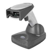
NCR RealScan 7875-7000/8000 Installation Guide
AIP-00342 Release B 06/03
11 of 56
Electrical Wiring to the Checkstand
Feeder wiring and insulated ground from
main service panel to distribution panel
to be run in metal conduit.
The electrical wiring must meet all
electrical codes, laws, and regulations.
Note:
Circuit Breakers
NCR circuits should be run in
separate metal Conduits.
Isolated/Insulated
Ground Bus
Isolated Ground Receptacles
Neutral and
Ground Bus
Neutral
Bus
Input
Voltage
Input Voltage L1, L2 Circuit Breakers
U.S., Canada, &
Japan
European
International
100Vac to 120Vac
220Vac
220Vac to 240Vac
100Vac to 120Vac
220Vac
220Vac to 240Vac
Standard single-pole; value
determined by type of device
branch and by electrical code.
European double-pole.
Circuit B: Terminal
Installation Type
NCR circuits must be dedicated to
NCR equipment or other logically
connected electronic equipment
(modems, DAA, bridges, etc.)
Note:
Circuit C: Scanner/Scale
Receptacle should be easily
accessible and near the
Scanner/Scale
L2
L3
Distribution Panel
Main Service
Panel
Conduit
Checkstand
Frame
Circuit A: Checkstand
Belt
Motor
Belt Control
Lighting
Misc. Equip.
N
G
L1
R0121
Note: The RealScan 7875 outlet in the checkstand must be connected to a circuit breaker switch.
This switch must be located close to the operator and is used as the On/Off switch for the
RealScan 7875.
 Loading...