NCR RealScan 7875-7000/8000 Installation Guide
AIP-00342 Release B 06/03
15 of 56
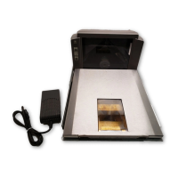
Connect Remaining Components
Locate the NCR RealScan 7875 Power Supply in position in the checkstand where spilled liquid
cannot contact it. The system configuration may also include a Remote Display and an RS-232
peripheral such as a hand-held scanner. The following illustration shows how all cables are
connected. Be sure to route these cables properly through the checkstand. After all cables are
connected, plug in the NCR RealScan 7875 and the Sensormatic ScanMax
TM
Pro Controller
Power Cords to supply power to the units.
20553
D
C
P
O
W
E
R
R
E
M
O
T
E
D
I
S
P
L
A
Y
5
A
M
A
X
S
C
A
N
N
E
R
Check switch settings
5
V
DC
Power
Cable
Remote
Display
AC
Power
Cord
Power
Supply
RealScan 7875
Interface
Cable
Host
Terminal
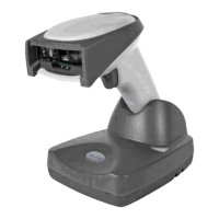
RS-232
Peripheral
BCAN I/O POS SERVICE REMOTE ANTENNAEXPANSIONBR
MNS
PROGSTATUS
PORT 1 PORT 2
DUAL PERIPHERAL PORTS
Sensormatic
ScanMax™
Pro Controller
Sensormatic
Communications Cable
Sensormatic
Antenna
Cable
AC
Power
Cord
 Loading...