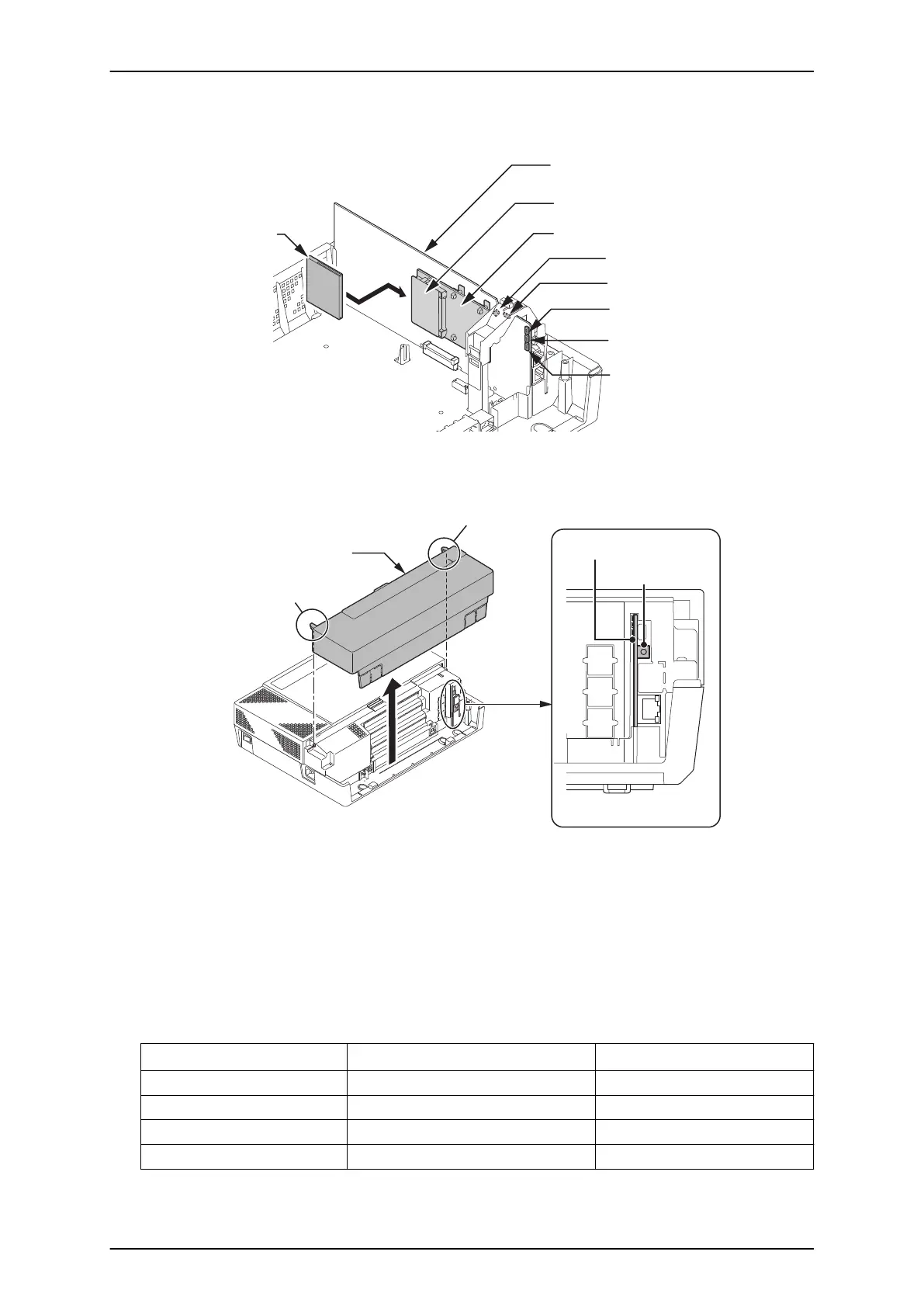
4. Insert the CF card (with the new main system software loaded) to the CF slot on PZ-VM21
daughter board. (PZ-VM21 should be temporary installed if not already fitted.)
CPU card
CF Slot (CN2)
CF card
PZ-VM21 PCB
D3 (Red)
D1 (Blue)
D2 (Red)
D4 (Red)
D5 (Red)
Figure 4-17 Inserting the CF card
5. Push in and hold the LOAD button (S1 on the CPU card).
Sub-Cover
Tab
< Front view >
S1
LOAD
CPU card
Tab
Figure 4-18 LOAD Button (S1) Location
6. Turn the system power on.
7. Continue holding the LOAD button (S1) for approximately 10 seconds or until Status LED (D5)
starts flashing red.
8. Release the LOAD button (S1).
9. Wait until the Status LEDs (D2 to D5) on the CPU card has the following indications
(approximately two minutes).
Table 4-1 Status LEDs
LED No.
Indication Remarks
D2 Flashing Red
D3 Flashing Red
D4 Flashing Red
D5 Off
SL1100 ISSUE 4.1 (R5.1)
4-10 Maintenance