uPASS Access | installation guide
10/
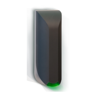
3 Connections
The uPASS Access is supplied with a 5 meter (15 feet) shielded cable with 12 multi-color wires.
Power supply 0VDC, DC-Ground.
Tamper switch (normally closed)
LED_NA_IN (NA = not authorized)
Nedap antenna interface. RFMOD antenna modulation (ANT/HF+).
Shield connected to DC-ground. Connect to metal case of the external device.
3.1 Power supply
The uPASS Access requires DC power supply in the range from 12 – 24V.
Maximum current consumption is 1A @ 12VDC, 1A @ 24VDC.
Connections
Power supply 0V / DC-ground.
Shield connected to DC-ground. Connect to metal case of the external device.
Notes
• The minimum voltage at the end of the included cable shall be greater than 12VDC.