Figures
1
4
4
7
8
8
8
9
9
9
10
11
11
15
16
16
17
17
18
18
19
19
20
20
21
21
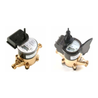
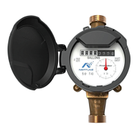
Figure 1 – E-CODER
®
)R900i™
Figure 2 – Inside Dimensions
Figure 3 – Antenna Dimensions
Figure 4 – E-CODER
®
)R900i™ Antenna
Figure 5 – Insert the Antenna into the Pit Lid
Figure 6 – Locking Nut on Antenna
Figure 7 – Secure the Locking Nut
Figure 8 – Installation Complete
Figure 9 – Remove the Protective Cap and Gasket
Figure 10 – Align the F Connector
Figure 11 – Seat the Connection
Figure 12 – Solar Panel for the E-CODER
®
)R900i™
Figure 13 – Activating the E-CODER®)R900i™
Figure 14 – HHU Home Screen
Figure 15 – N_SIGHT
®
R900 Menu Screen
Figure 16 – Data Logger Option
Figure 17 – Reader ID Input
Figure 18 – HHU Time Confirmation
Figure 19 – Initialize RF Device
Figure 20 – Enter MIU ID
Figure 21 – Capture Button
Figure 22 – Unit of Measure and Meter Size
Figure 23 – Start Button
Figure 24 – E-CODER
®
)R900i™ Listens for Data
Figure 25 – E-CODER
®
)R900i™ Receives Data
Figure 26 – Graph Button
Figure 27 – Example Data Logging Graphs
22
E-CODER
®
)R900
i
™ Installation and Maintenance Guide vii