Model H1301 Recovery and Recycling System
Installation, Operation and Maintenance Manual
Revision-L September, 2019
Page 29 of 105
V. System Operations and Controls
C. Inlet Pressure Switch Function and Adjustment (continued)
Inlet Pressure Switch Adjustment Procedure
Required Materials:
Clean Dry Commercial Grade Nitrogen Gas Regulated from 25 to 250 psi Max.
Connection plumbing from the Nitrogen Source to the Inlet Port of the machine
Screwdriver
3/8” Open End Wrench
NOTE: The set point of the pressure switch is adjustable from 10 to 100 psig. The set
point is decreased by rotating the switch adjustment screw counterclockwise and
increased with a clockwise rotation of the adjustment screw.
NOTE: The control panel hood may be removed to gain easy access to the switch and
to observe the PLC status indicators. Otherwise, the switch is accessible through the
filter access door and the PLC status indicators may be viewed using an inspection
mirror.
1. Place the power switch of the machine to the off position. Disconnect the main electrical
power from the machine.
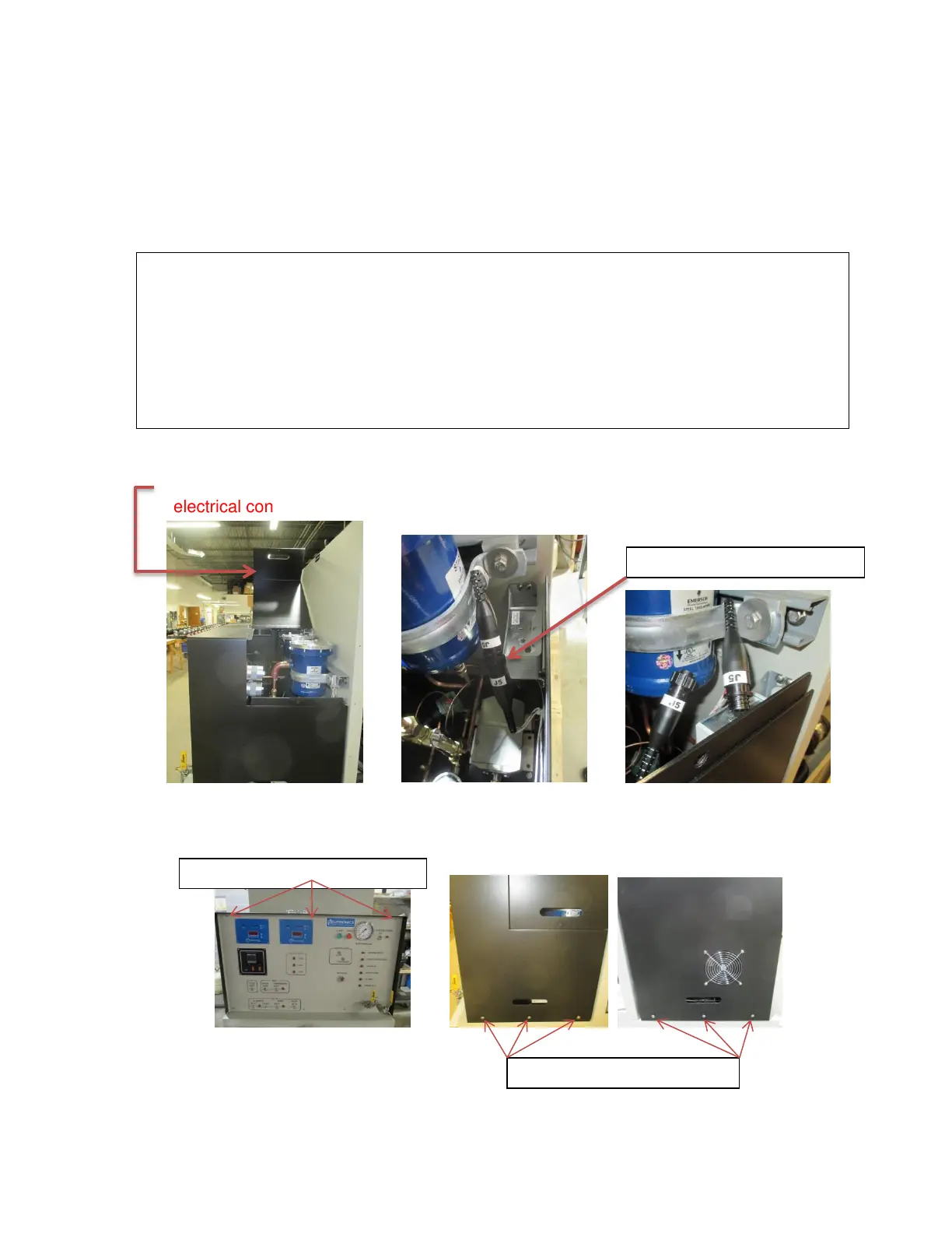
2. Open the filter access door of the hood and separate the two halves of the hood fan
electrical connector J5.
3. Remove the three screws along the top of the control panel and the three screws on
both sides of the control panel hood. With a helper, lift the hood up and over the control
panel.
Rotate the knurled ring to unlock
Three screws both bottom sides
Three screws top of Control Panel