Model H1301 Recovery and Recycling System
Installation, Operation and Maintenance Manual
Revision-L September, 2019
Page 30 of 105
V. System Operations and Controls
C. Inlet Pressure Switch Function and Adjustment (continued)
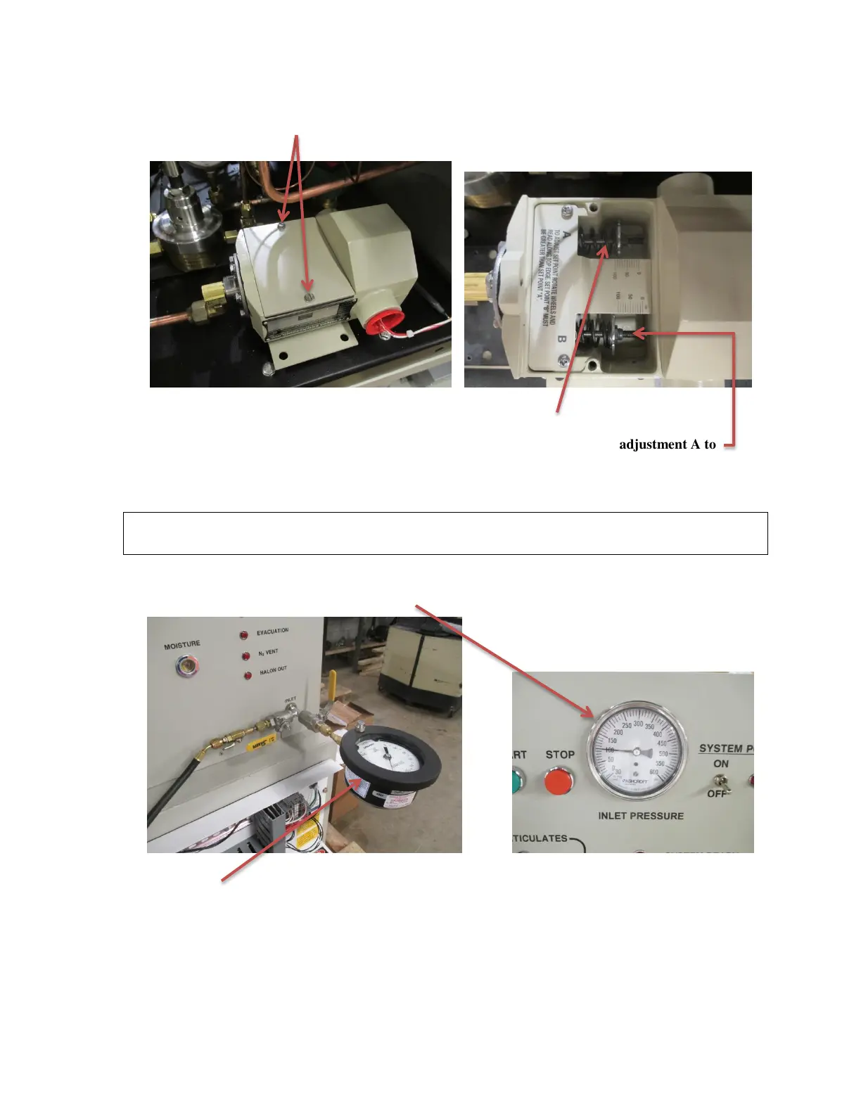
4. Remove the two screws that retain the cover of the pressure switch.
5. Remove the cover and gasket to gain access to the adjustments.
NOTE: B adjustment screw is not used and must be set to over 100 psi to allow adjustment A to
travel the full range.
6. Connect the main electrical power back to the machine.
7. Place the machine power switch to the ON position.
WARNING! Do not touch or place any body part onto any of the electrical connections
or wiring with power applied to the machine.
8. A source of dry nitrogen can be used to pressurize the inlet port of the machine, with
the manual inlet valve open, until the desired actuation pressure is achieved as
indicated by the inlet pressure gauge.
An external gauge may be connected to the opposite valve for finer adjustment. Close the
manual inlet valve to maintain the desired pressure.