Model H1301 Recovery and Recycling System
Installation, Operation and Maintenance Manual
Revision-L September, 2019
Page 31 of 105
V. System Operations and Controls
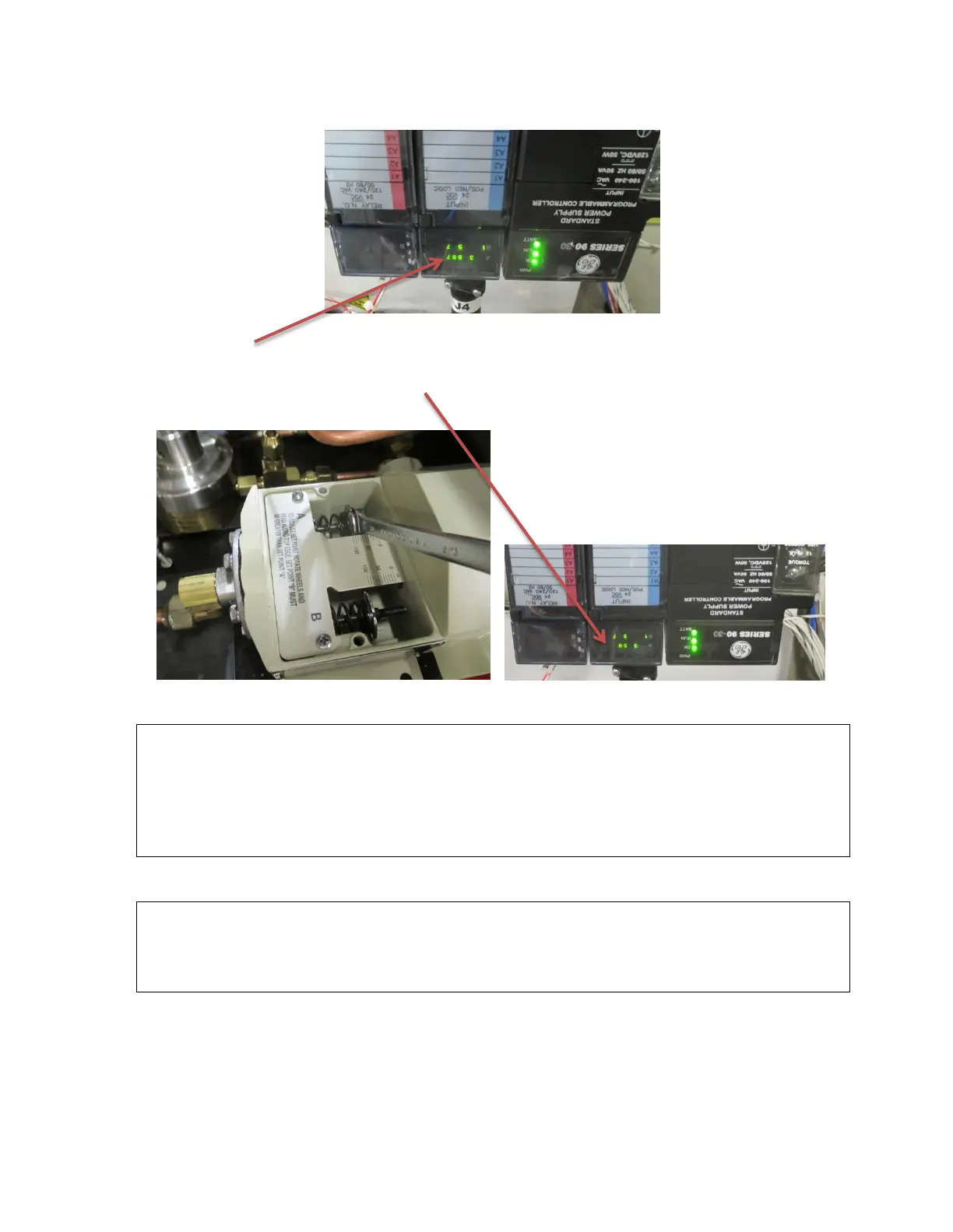
C. Inlet Pressure Switch Function and Adjustment (continued)
9. If the #A7 status indicator of the PLC input display is illuminated: rotate the pressure
switch A adjustment screw to decrease the pressure using a 3/8” end wrench until the
#A7 status lamp of the PLC goes out.
10. If the #A7 indicator is not illuminated: slowly rotate the adjustment screw to increase
the pressure and stop when the #A7 indicator illuminates.
NOTE: The pressure set point of the switch should then be checked and readjusted as
required by pressurizing the inlet plumbing of the machine until the #A7 indicator goes
out and then slowly releasing pressure from the manual inlet valve while observing the
#A7 indicator and the inlet pressure gauge. The #A7 indicator should not be
illuminated at pressures higher than the desired set point and should illuminate at the
desired pressure as the pressure is decreased.
11. Disconnect power from the machine reinstall the pressure switch cover, the hood and
reconnect the fan electrical connector.
CAUTION: The inlet pressure switch must always be adjusted to no lower than 10 psi
below the Alarm #1 pressure setting of the control panel Pressure
Controller. For example: if the pressure controller alarm #1 set point is set
to 50 then the lowest setting for the inlet pressure switch would be 40psig.
Recommended Pressure Settings
Halon 1301 and FE25 100 psi
Halon 1211 15 psi
FM200 20 psi