Model H1301 Recovery and Recycling System
Installation, Operation and Maintenance Manual
Revision-L September, 2019
Page 66 of 105
VII. System Maintenance Procedures (continued)
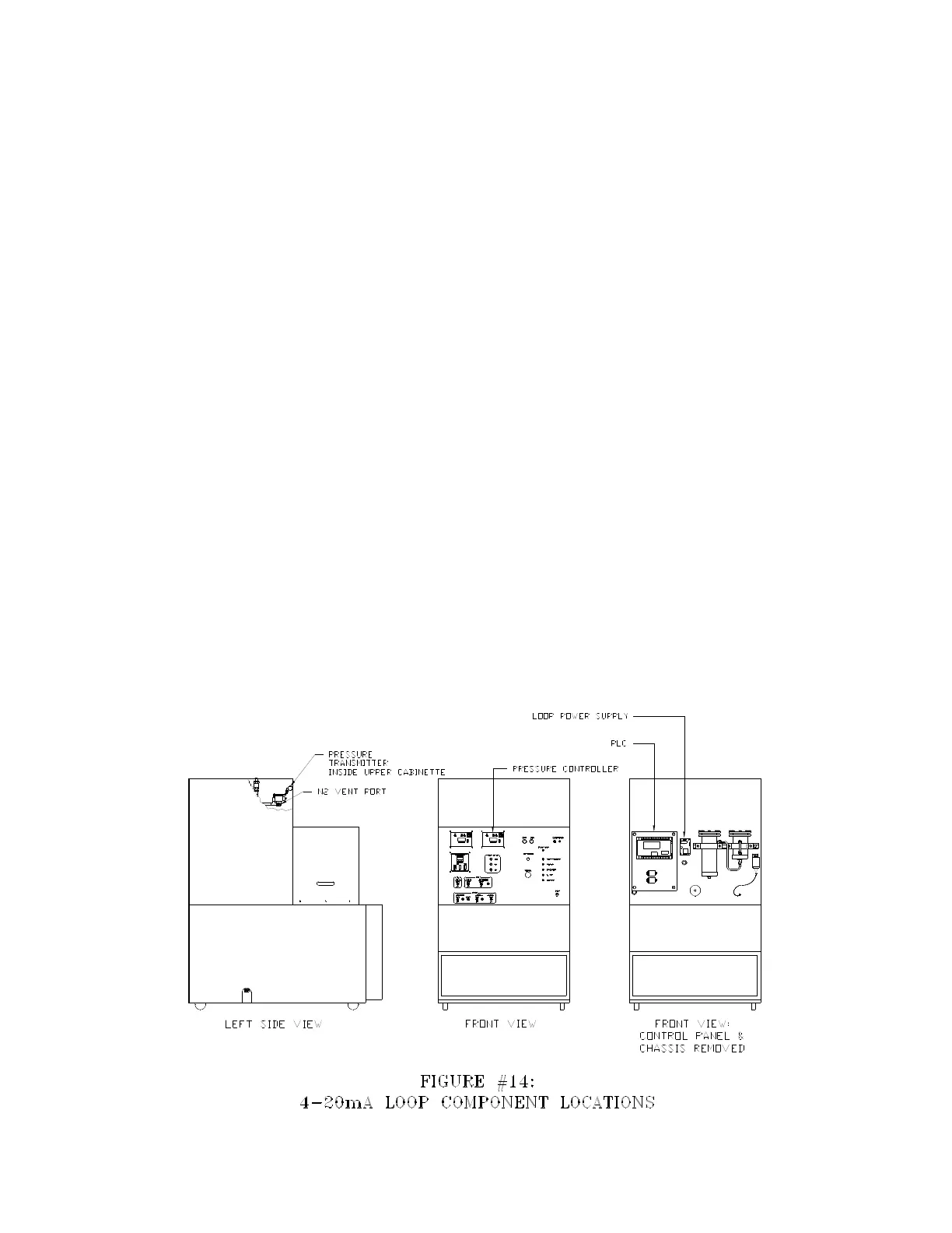
M. Pressure Controller Adjustment and Calibration
The pressure in the Process Tank is monitored by a 4-20mA-loop system consisting of
three main components. Refer to figure #14 for the mounting locations of these
components. The power supply provides the low voltage DC power to drive the loop
system. The pressure transmitter is the pressure-sensing device for the process tank.
The front panel pressure controller receives the transmitter signal, displays the
processing tank pressure, and communicates the tank pressure to the system PLC via
two alarm outputs. The calibration of the system is critical for the correct operation of the
machine.
Power Supply part number 6-01-1000-10-0
Specifications:
Input Power 100-130 VAC 50/60 Hz
Output 12 VDC 6-WATTS
Pressure Transmitter part number 1-16-3026-00-0
Specifications:
0 to 250 PSIA operating range, 500 PSIA over-pressure
Input Power 12 Volts DC @20mA
Output Signal 4-20mA corresponding to 0-250 PSIA
Pressure Controller part number 7-06-1300-00-0
Specifications:
Input Power 104-130 VAC 50/60 Hz
Signal Input 4-20mA
Two Adjustable Relay Contact Alarm Outputs
0 to 2.5 VDC Signal Output Corresponding to 0 to 250 psia
3 1/2 Digit LED Display