Model H1301 Recovery and Recycling System
Installation, Operation and Maintenance Manual
Revision-L September, 2019
Page 67 of 105
VII. System Maintenance Procedures
M. Pressure Controller Adjustment and Calibration (continued)
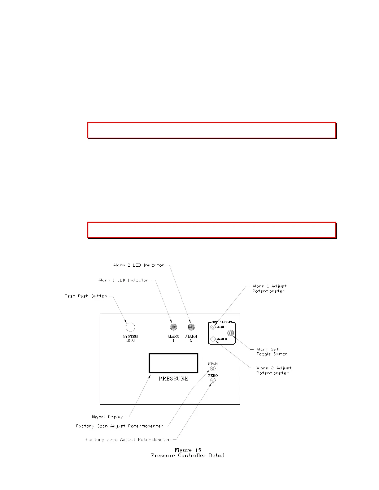
1. Alarm Set Point Adjustment: Reference figure-15
To Adjust Alarm #1:
a. Place the front panel Power Switch to the ON Position.
b. Position and hold the Alarm Set Switch to the Alarm 1 position. The alarm 1 set
point will be displayed on the pressure controller display.
c. Use a calibration screwdriver to adjust the alarm 1 potentiometer to the desired set
point.
The factory set point for alarm #1 is 50 psia. The Alarm #1 LED will be illuminated
above the set point.
d. Release the Alarm Set Switch and the display will return to the pressure reading of
the process tank.
To Adjust Alarm #2:
a. Place the front panel Power Switch to the ON Position.
b. Position and hold the Alarm Set Switch to the Alarm 2 position. The alarm 2 set
point will be displayed on the pressure controller display.
c. Use a calibration screwdriver to adjust the alarm 2 potentiometer to the desired set
point.
The factory set point for alarm #2 is 25 psia. The Alarm #2 LED will be illuminated
below the set point.
d. Release the Alarm Set Switch and the display will return to the pressure reading of
the process tank.