Model H1301 Recovery and Recycling System
Installation, Operation and Maintenance Manual
Revision-L September, 2019
Page 70 of 105
VII. System Maintenance Procedures
M. Pressure Controller Adjustment and Calibration (continued)
3. Pressure Loop Power Supply Troubleshooting
The following procedure will detail how to verify correct operation of the pressure loop
system power supply. If the criteria listed below are not obtainable then the power supply
must be replaced. Consult the factory for replacement.
Required Materials:
Straight Blade Screwdriver
499 ohm ½ watt resistor
Voltmeter: 20 VDC and 200 VAC Ranges
a. Place the System Power Switch to the OFF Position.
b. Disconnect the main electrical power from the machine.
c. Open the filter access door of the hood and separate the two halves of the hood
fan electrical connector.
d. Remove the three screws along the top of the control panel and the three screws
on both sides of the control panel hood. With a helper, lift the hood up and over the
control panel.
e. Place all of the Front Panel Control Switches to the AUTO position.
f. Place the Cooling System Controller Power Switch to the OFF position.
g. Connect Main Power to the machine.
h. Place the System Power Switch to the ON position.
WARNING! THE AREA INSIDE THE CONTROL PANEL HOOD CONTAINS
120VAC POWER CONNECTIONS; DO NOT REST ANY PART OF
YOUR BODY ON ANY OF THE INTERNAL COMPONENTS.
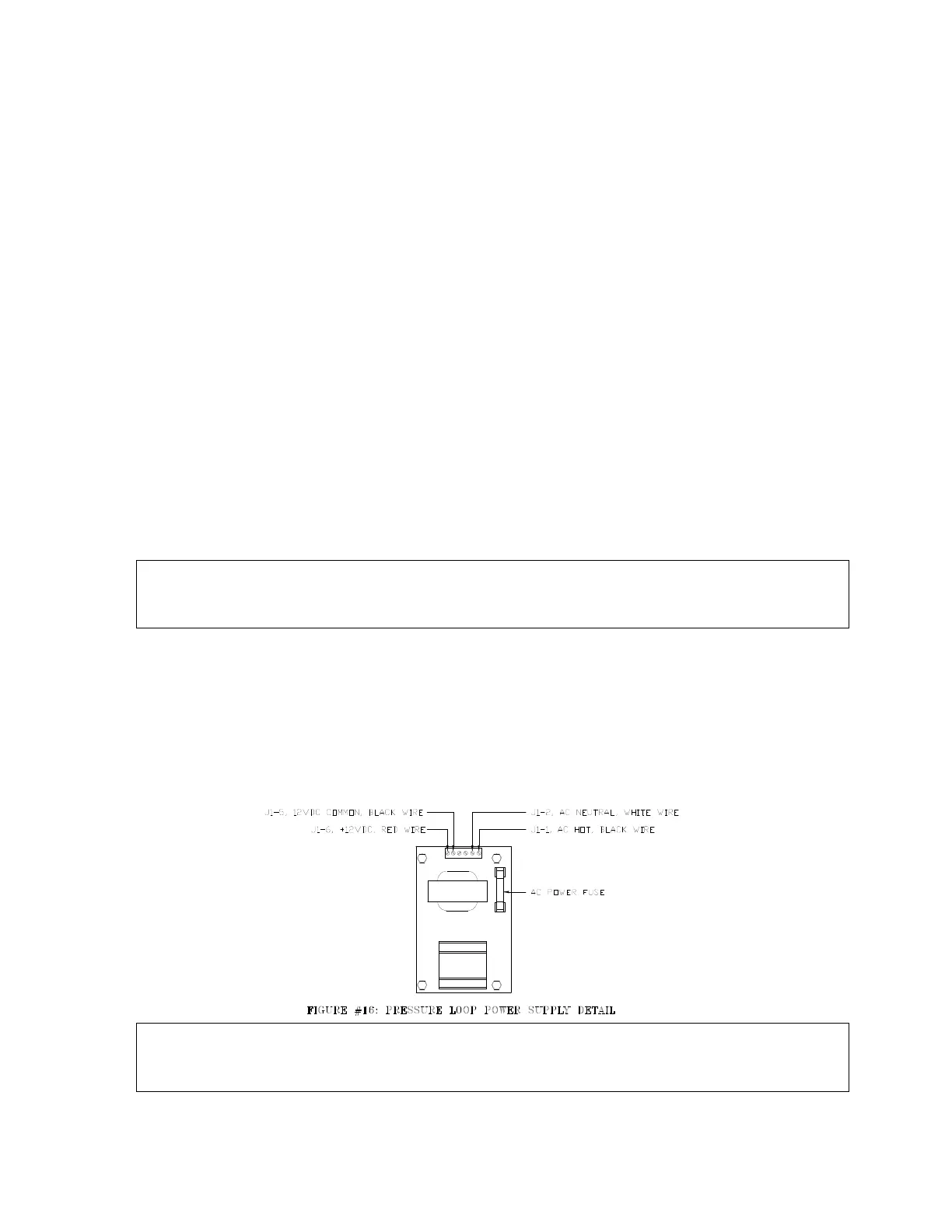
i. Using the Voltmeter, configured for AC voltage measurement, verify 100 to 130
VAC between J1-1 and J1-2 at the Loop Power Supply J1 connector refer to
figure 16.
j. Using the Voltmeter, configured for DC voltage measurement, verify 12 +\-0.6 VDC
at the Loop Power Supply J1 connector. Refer to figure 16 and connect the
Voltmeter as follows:
Voltmeter Positive Probe to J1-6
Voltmeter Negative Probe to J1-5
NOTE: If the voltage is within the specified range continue with the Section-3:
Pressure Transmitter Trouble Shooting Guide. If the voltage is greater than 12.6VDC
or less than 11.4VDC: continue with this procedure.



 To Next Page