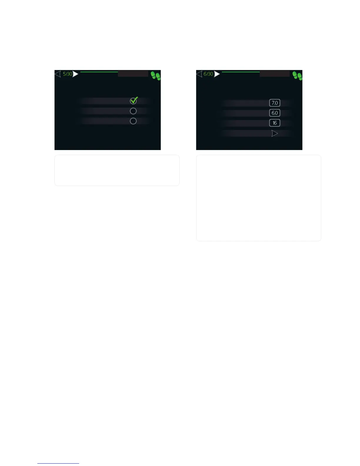
5 Setting "op. mod heat med pump"
VWDUW JXLGH
DXWR
LQWHUPLWWHQW
FRQWLQXRXV
RS PRG KHDW PHG SXPS
op. mode
Setting range: auto, intermittent, continuous
Default value: auto
Set the operating mode of the heating medium pump
here.
auto: The heating medium pump runs according to the
current operating mode for F1245.
intermittent: The heating medium pump starts 20
seconds before and stops at the same time as the com-
pressor.
continuous: Continuous operation.
6 Setting "internal electrical addition"
VWDUW JXLGH
IXVH VL]H
VHW PD[ HOHFWULFDO DGG
LQWHUQDO HOHFWULFDO DGGLWLRQ
$
N:
GHWHFW SKDVH RUGHU
3KDVH VHTXHQFH QRW IRXQG
PD[ FRQQHFWHG HO DGG
N:
max connected el. add.
Setting range: 7/9kW
Default values: 7 kW
set max electrical add.
Setting range: 0 - 9 kW
Default values: 6 kW
fuse size
Setting range: 1 - 200 A
Default values: 16 A
Here you set the max. electrical output of the internal
electrical addition in F1245 and the fuse size for the in-
stallation.
Here you can also check which current sensor is installed
on which incoming phase to the property (this requires
current sensors to be installed, see page 23). This is
achieved by marking "detect phase order" and pressing
the OK button.
The results of these checks appear just below where the
checks were activated.
NIBE™ F1245Chapter 6 | Commissioning and adjusting30

 Loading...


